EasyManua.ls Logo

PowMr POW-LVM2K-12V - User Manual

PowMr POW-LVM2K-12V
23 pages
Print Icon
To Next Page IconTo Next Page
Loading...
POW-LVM2K-12V
POW-HVM2K-12V
POW-LVM3K-12V
POW-HVM3K-12V
INVERTER CHARGER
User Manual
Question and Answer IconNeed help?

Do you have a question about the PowMr POW-LVM2K-12V and is the answer not in the manual?

Summary

Safety Instructions

General Safety Information

Installation and general precautions for safe operation of the inverter.

Inverter Safety

Specific safety guidelines for inverter operation and connection.

Battery Safety

Precautions for handling and charging batteries with the inverter.

Installation Safety

Environmental and physical installation safety requirements for the unit.

General Information

Key Features

Highlights the main functionalities and design aspects of the inverter.

Pure Sine Wave Technology

Explains the waveform output and its benefits for sensitive electronics.

Introduction

Basic System Architecture

Illustrates the internal components and their connections in the system.

Working Mode Instructions

Details how the inverter operates in different priority modes.

Electric Supply Priority Mode

Describes operation when utility power is prioritized over battery power.

Product Features Overview

Lists the key technical characteristics and capabilities of the inverter.

Product Overview

Top View Diagram

Provides a visual representation of the inverter's top panel layout.

Real View Diagram

Shows a detailed view of the inverter's physical connections and ports.

Operation

Battery Charging Stages

Explains the different phases of the battery charging process.

Operation and Display Panel

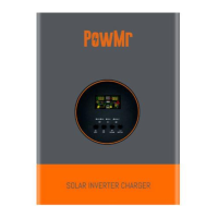
Describes the front panel controls, indicators, and LCD display.

LCD Display Icons Explained

Details the meaning of various icons shown on the inverter's LCD screen.

LCD Setting and Configuration

Configuration Options

Set basic inverter configurations like priority, input range, power saving, and battery type.

Operational Parameters

Configure operational parameters such as auto-restart, frequency, and low battery transfer.

Advanced Settings

Adjust advanced settings including voltage recovery, alarms, display, and charging.

Battery Management Settings

Configure specific battery management features like charging voltage and trip points.

System Control Settings

Configure system controls like dry contact, low battery alarms, and output voltage.

Fault Reference Code

Specifications

Inverter Mode Specifications

Details performance parameters in inverter operation mode.

Line Mode Specifications

Details performance parameters in line (utility) mode.

Battery Charging Voltage Selection

Lists charging voltages for different battery types.

Dimensions

Overview

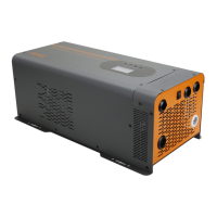
The PowMr Pure Sine Wave Power Inverter Charger is a versatile device designed to provide reliable electricity for remote off-grid applications. It functions as both an inverter and a charger, delivering clean, smooth, and stable power similar to grid electricity. This makes it suitable for a wide range of electronic devices, from tools and fans to lights and computers, without causing interference. The inverter is capable of charging a battery bank when AC power is connected, enhancing its utility in various setups.

Function Description

The core function of this device is to convert DC power from batteries into AC power, specifically a pure sine wave, which is crucial for sensitive electronics. It also incorporates a charging function to replenish battery banks. The inverter operates in different modes, primarily "Inversion priority mode" and "Electric supply priority mode," to optimize power delivery and battery management.

In Inversion priority mode, the inverter primarily draws power from the battery bank to supply the load. This mode is active when the battery voltage is normal. If the battery is fully charged by solar or wind energy through a controller, the system automatically switches to battery-powered mode. The battery can also be charged in this mode if the inverter is operating under electric supply, with the charging current being configurable (including 0A if charging is not needed).

In Electric supply priority mode, the load is primarily powered by the electric supply. The electric supply passes through an input protection device and a filter to ensure power stability before reaching the load. In this mode, the battery can also be charged, depending on the configured charging mode. If there's an outage or abnormality in the electric supply, the system automatically switches to battery-powered mode. Once the electric supply returns to normal, the system reverts to electric supply mode to power the load.

The device features a 4-stage battery charger with a configurable charging current, allowing users to tailor the charging process to their specific battery type and application. It supports 8 pre-set battery voltages, including Lithium, and offers a user-defined option for greater flexibility. An automatic generator start option is also available, providing an additional layer of reliability for power generation.

Usage Features

The PowMr inverter charger is designed for ease of use and monitoring. It features an LCD and LED display that provides comprehensive information about the inverter's status and allows for programming. The LCD display shows input voltage, input frequency, PV voltage, battery voltage, and charger current. It also indicates setting programs, warning codes, and fault codes. For output information, the LCD displays output voltage, output frequency, load percentage, load in VA, load in Watt, and discharging current. Battery information, including charge level (0-24%, 25-49%, 50-74%, and 75-100%) and charging status, is also clearly presented.

The LED indicators provide quick visual cues:

  • AC/INV (Green): Solid On indicates output is powered by utility in Line mode; Flashing indicates output is powered by battery or PV in battery mode.
  • CHG (Green): Solid On indicates the battery is fully charged; Flashing indicates the battery is charging.
  • FAULT (Red): Solid On indicates a fault in the inverter; Flashing indicates a warning condition.

Four function keys (ESC, UP, DOWN, ENTER) facilitate navigation and setting adjustments within the LCD menu. Pressing and holding the ENTER button for 3 seconds enters the setting mode, where users can select programs using UP/DOWN and confirm with ENTER or exit with ESC.

Key configurable settings include:

  • Output source priority: Users can choose between "Utility first" (default) or "Battery priority." Utility first ensures the utility provides power as the primary source, with battery power used only when utility power is unavailable. Battery priority prioritizes battery power, with utility power used only when battery voltage drops to a low-level warning or a specific setting point.
  • Input voltage range: Options for "Wide" (nominal output voltage: -23% to +15%) or "Narrow" (default, nominal output voltage: -15% to +15%) utility effective range.
  • Power saving mode: Can be "disabled" (default), meaning the inverter output is unaffected by low or high connected load, or "enabled," which turns off the inverter output when the connected load is very low or not detected.
  • Battery type: Supports various battery types including Gel U.S.A, A.G.M.1, A.G.M.2, Sealed Lead Acid, Gel Euro, Open Lead Acid, Calcium, Desulphation, and Lithium. A "User-defined" option is also available, allowing for custom battery settings.
  • Auto restart when over temperature occurs: Can be "disabled" (default) or "enabled."
  • Output frequency: Configurable to 50Hz (default) or 60Hz.
  • Maximum utility charging current: Adjustable with a 5A base, from 0A up to a maximum value determined by the inverter's output power and DC voltage.
  • Low battery voltage inverter transfer to Utility: Sets the alarm point for low battery voltage before transferring to utility power. The default range is 10.5V to 12.5V for 12V systems (scaled for 24V/48V).
  • High battery voltage recovery: Sets the battery voltage at which the output of the battery model is activated (if set higher than 13.5V-15.5V) or bypass output is activated (if set from 13.0V to 15.5V).
  • Alarm control: Can be "on" (default) or "off."
  • Auto return to default display screen: "Return to default display screen" (default) automatically reverts to input/output voltage display after 1 minute of inactivity. "Stay at latest screen" keeps the display on the last screen the user switched to.
  • Backlight control: Can be "on" (default) or "off."
  • Beeps while primary source is interrupted: Can be "on" (default) or "off."
  • Record Fault code: Can be "enable" (default) or "disable."
  • Bulk charging voltage (C.V voltage): Configurable if "User-defined" battery type is selected, with a range from 13.0V to 15.5V for 12V systems.
  • Maximum charging voltage for lithium battery: Configurable if "User-defined" battery type is selected, with a range from 13.0V-15.5V.
  • Floating charging voltage: Configurable if "User-defined" battery type is selected, with a range from 13.0V to 15.0V for 12V systems.
  • Battery low voltage open charging (for lithium battery): Configurable if "User-defined" battery type is selected, with a range from 12.0V to 14.0V for 12V systems.
  • Low DC cut-off voltage: Default is 10.0V, with a setting range from 10.0V to 12V for 12V systems.
  • Frequency Range: Options for "Special 40-70HZ" or "General 50HZ 45-55HZ/60HZ 55-65HZ."
  • Selection of battery type: Allows choosing between "Lithium battery" or "Other battery," which then enables specific charging voltage settings.
  • Battery high voltage trip: Sets the battery voltage point at which the dry contact switch changes from NC to NO. This setting cannot be higher than the fast charge voltage.
  • Dry contact control: If set to "dcd," the dry contact function is disabled. If set to "dce," the dry contact function is enabled, allowing settings for battery high voltage trip and low battery voltage trip.
  • Low battery alarm: Sets the low battery voltage shutdown point. The default is 10.5V, with a range from 10.5V to 12.5V for 12V systems.
  • Output voltage setting: Configurable to 120V or 230V, with a range from 100V/200V to 120V/240V.

Maintenance Features

The device incorporates several safety and protection features to ensure reliable operation and longevity. These include:

  • Over temperature auto restart: The inverter can automatically restart if it experiences an over-temperature condition.
  • Overload protection: The device is designed to handle temporary overloads, with specific fault responses depending on the load percentage and duration. For instance, loads between 105% and 120% of nominal output power will trigger a fault after 10 seconds, while loads above 150% will trigger a fault after 1 second.
  • Short circuit protection: Software-based protection is implemented to prevent damage from short circuits.
  • Multiple electronic protections: Beyond overload and short circuit, the inverter includes protections against battery overcharge, low battery voltage, PV input voltage too low/high, PV over current, PV over temperature, transformer phase reversal, and frequency out of range.
  • Fault Reference Code: The device provides specific fault codes (e.g., 02 for Inverter over temperature, 03 for Battery voltage overcharge, 04 for Battery voltage is too low) and warning codes (e.g., 12 for PV input voltage is too low, 13 for PV input voltage is too higher) displayed on the LCD, aiding in troubleshooting.
  • Installation Safety: The manual emphasizes the importance of proper installation in a well-ventilated, cool, and dry environment, ensuring that fans and ventilation holes are not blocked. It also warns against exposing the unit to rain, moisture, snow, or liquids.
  • Battery Safety: Guidelines are provided for safe battery handling, including not allowing positive and negative terminals to touch, using deep cycle batteries (sealed Lead-Acid, Flooded, Gel, AGM, Lithium, or Calcium), ensuring adequate ventilation during charging to release explosive battery gases, wearing eye protection when working with large lead-acid batteries, and being cautious of high lethal voltages retained by capacitors even after power removal. It also advises against over-charging and excessive gas precipitation, which can damage battery plates.

The PowMr inverter charger is a robust and sleekly designed unit with an efficiency exceeding 90%, making it an effective solution for off-grid power needs. Its comprehensive display, configurable settings, and integrated safety features contribute to its user-friendliness and reliability.

PowMr POW-LVM2K-12V Specifications

General IconGeneral
ModelPOW-LVM2K-12V
Input Voltage230 VAC
Frequency Range50 Hz/60 Hz (Auto sensing)
Output Voltage Regulation230 VAC ± 5%
Output Voltage230 VAC
Surge Power4000VA
Efficiency (Peak)93%
WaveformPure sine wave
Battery Voltage12 VDC
Floating Charge Voltage13.5 VDC
Humidity5% to 95% Relative Humidity (Non-condensing)
DisplayLCD
Charging TypeMPPT
Selectable Voltage Range170-280 VAC (For Personal Computers) / 90-280 VAC (For Home Appliances)
Transfer Time10 ms (For Personal Computers) / 20 ms (For Home Appliances)
PV Array MPPT Voltage Range30~80VDC
Operating Temperature Range0°C - 55°C
Storage Temperature Range-15°C~60°C
Battery TypeLead-acid or Lithium
Protection FeaturesOverload, Short Circuit, Overcharge, Over-temperature
Battery Type CompatibilityLead-acid or Lithium

Related product manuals