Chapter 5 Function parameter
103
Used to set the inverter's current sensing compensation, if the set value is too large, which
may reduce the control performance. Generally do not need to be modified.
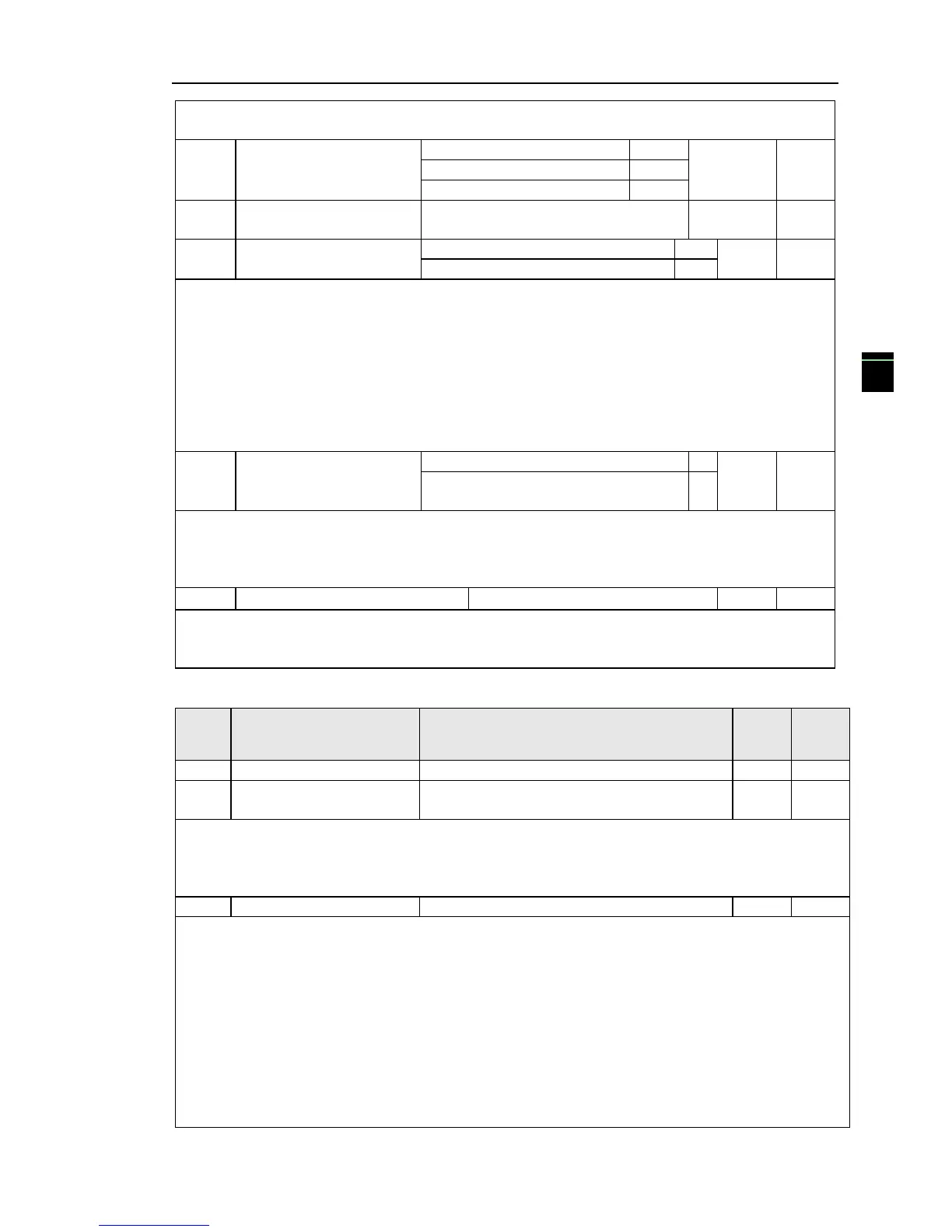
Vector optimization
without PG mode selection
Upper limiting frequency
for DPWM switching
Only valid for V/F control. Synchronous modulation refers to that the carrier frequency
linearly change with the change of output frequency, in order to ensure the unchanged of their
ratio(carrier to noise ratio), generally it is used when the output frequency is higher, is conducive
to ensure the output voltage quality.
Under the lower output frequency (100Hz) mode, generally the synchronize modulation is not
required, because at the time the ratio of the carrier frequency to the output frequency is relatively
high, the asynchronous modulation has more obvious advantages.
When the operating frequency is higher than 85Hz, the synchronous modulation takes effect,
the fixed mode is the asynchronous modulation below the frequency.
PWM carrier frequency random depth
By setting Random PWM, the monotonous and shrill motor sound can become softer and
which helps reduce external electromagnetic interference. When Random PWM Depth is set to 0,
Random PWM will be invalid.
It will get different results by adjusting different Random PWM Depths,
About 1140V voltage setting, the voltage availability will be improved by adjust voltage
setting. Too lower value setting can lead to system instability. So it is not recommended to revise it
for users.
5-2-14.Extended parameter: FC.00-FC.02
Proportional linkage
coefficient
When proportional linkage coefficient is 0, proportional linkage function can not
work.According to the setting by proportional linkage, communication address of master (F9.02) is
set to 248, and communication address of slave is set to 1 to 247.Slave output frequency = Master
setting frequency * Proportional linkage coefficient + UP/DOWN Changes.
If the absolute value of deviation between PID setting source and feedback source is greater
than of the parameter, the inverter starts only when PID output frequency is greater than the wake-up
frequency to prevent the repetition of the inverter starts.If the inverter is operating, when PID
feedback source is greater than setting source and the output frequency is less than or equal to
(F7.48) sleep frequency, the inverter goes to sleep after (F7.49) delay time and performs free stop.
If the inverter is in the state of sleep and the current run command is valid, the absolute value of
deviation between PID setting source and feedback source is greater than of PID start deviation
(FC.02), when PID setting frequency is greater than or equal to F7.46 wake-up frequency, the
inverter will start after (F7.47) delay time.
If you want to use the function of PID start deviation, PID stop computing status must be set to
active (E2.27 = 1).

 Loading...


