6
3. Place unit in a vertical position with the Fertilizer Hopper facing up, place the Bolt into the Fertilizer Lever,
then into the corresponding hole in the Hopper. Push the 1/4‖ Flat Threaded Plate up into position. Attach
the Bolt to the Plate. See Figure 3.
Hopper
Fertilizer Lever
1/4‖ x 3/4‖ Hex Head Bolt
1/4‖ Flat Threaded Plate
Cross Section of Fertilizer Hopper
Figure 3
7
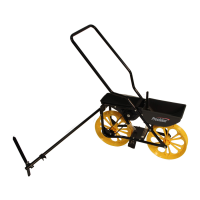
4. Assemble Row Marker to Row Marker Tube with 1/4‖ x 5/8‖ Carriage Bolt and 1/4‖ Wing Nut. Place Marker
Row Tube Cap on end of Row Marker Tube. See Figure 4.
Figure 4
Marker Row Tube
Marker Row Tube Cap
1/4‖ Wing Nut
1/4‖ x 5/8‖ Carriage
Bolt
1/4‖ Special
Nut
10-24 x 1/2‖ Slotted Pan Screw