EasyManuals Logo

PREVOST DEA700 User Manual

PREVOST DEA700
19 pages
To Next Page IconTo Next Page
To Previous Page IconTo Previous Page
Page #4 background imageLoading...
Page #4 background image
4 | P a g e
DEA7XX Radios System
Introduction
The information within this manual describes all
the features that may or may not be on your
specific radio either because they are options
that you did not purchase or due to changes
subsequent to the printing of this owner manual.
Overview
The Radio system is controlled by using the
buttons, RSA or steering wheel controls.
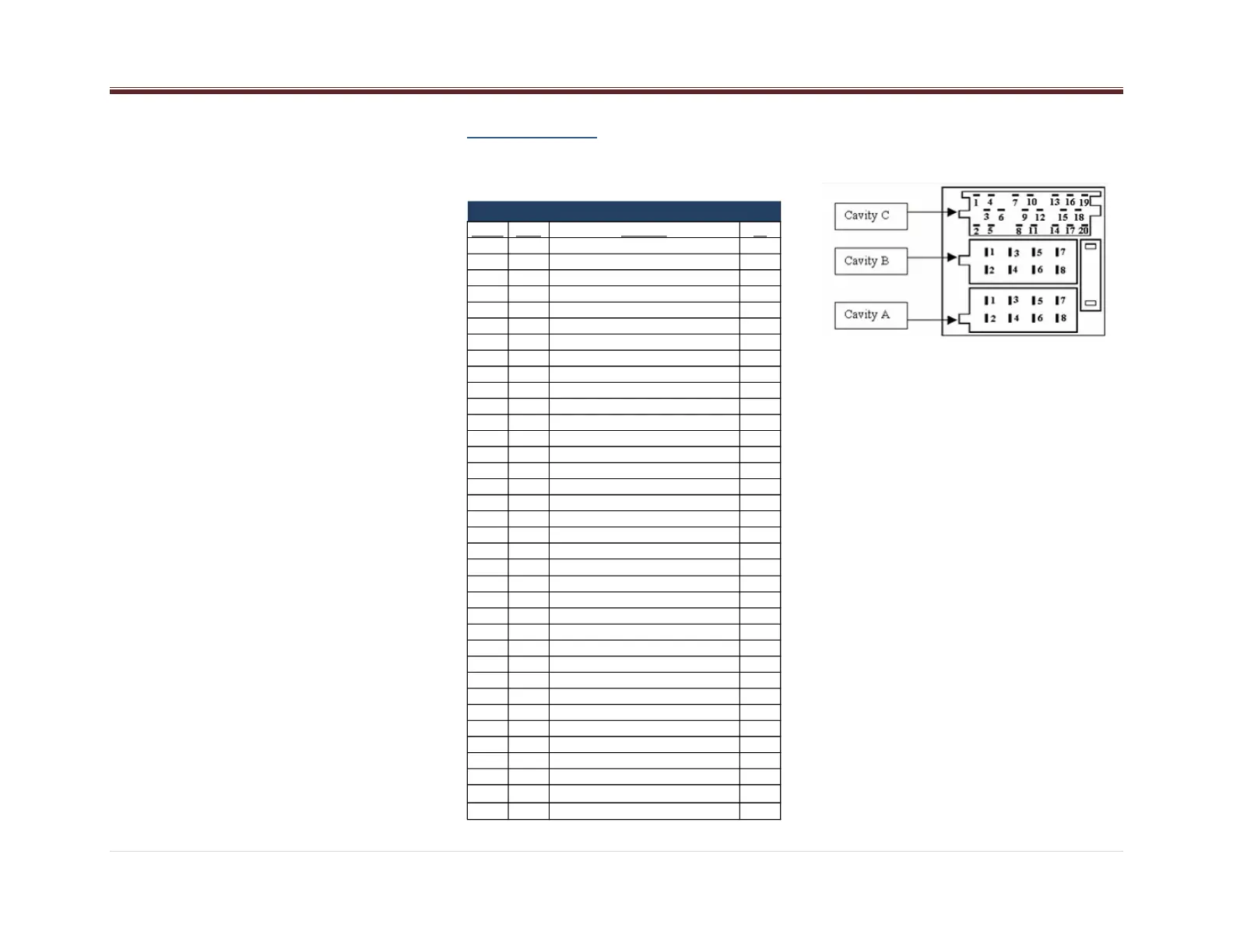
Radio Pinout
Radio pinout is shown below
Cavity Pin # Function I/O
A1 1 CAN-High I/O
A2 2 CAN-Low I/O
A3 3 Park Lights I
A4 4 Ignition I
A5 5 PWR_ANT/PA_MIC_PWR O
A6 6 Dim PWM/ANALOG I
A7 7 Battery I
A8 8 Power Ground -
B1 9 RR+ (Speaker) O
B2 10 RR- (Speaker) O
B3 11 RF+ (Speaker) O
B6 14 LF- (Speaker) O
B7 15 LR+ (Speaker) O
B8 16 LR- (Speaker) O
C1 17 Spare for future use -
C2 18 Amp Sense I
C3 19 Spare for future use -
C4 20 Cell_Tel_Mute I
C5 21 ASWC (Analog Steering Wheel Control) I
10 22 Power Ground -
C7 23 L_AUX_IN 2 I
C8 24 AUX_SHIELD_GND I
C9 25 AUX 2_COM I
C10 26 R_AUX_IN 2 I
C11 27 AUX 2_ON_OFF I
C12 28 Spare for future use -
C13 29 Spare for future use -
C14 30 Spare for future use -
C15 31 MIC + (BT) I
C16 32 MIC – (BT) I
C17 33 Spare for future use -
C18 34 Audio (+) PA MIC I
C19 35 MIC_ON Active Low Input (PA+ Input) I
C20 36 GND (PA- Input) I
REGULAR PANA PINOUT

Questions and Answers:

Question and Answer IconNeed help?

Do you have a question about the PREVOST DEA700 and is the answer not in the manual?

PREVOST DEA700 Specifications

General IconGeneral
BrandPREVOST
ModelDEA700
CategoryRadio
LanguageEnglish