Hello, and welcome to the world of XC-M tripods! You have purchased a ne tool designed for passionate
photographers. A tripod is a terric device for not only holding your camera steady; but, it is also as a great
compositional aid. We hope this new XC-M tripod kit will elevate your camera and your images!
Please read through this instruction guide thoroughly, even if you have operated other types of tripods
before, as the XC-M’s controls may dier. We want your experience with this dandy new XC-M to be as
fantastic as possible.
This manual begins with an explanation of how to operate the XC-M legs and ball head before it addresses
attaching your camera. We recommend learning these operation and controls without a camera attached
rst. Your camera is valuable and by knowing how to handle this tripod kit properly you can prevent acci-
dental damage from misuse.
Be sure to refer to the main parts diagram as well as each of the numbered gures as you read so you can
understand the names of all of the parts referred to. Whenever a specic part of the XC-M is referred to in
red, you will nd it shown on the main parts diagram and/or in the referenced gure. When a gure is used
to more specically demonstrate something, it is listed, by number, in parentheses in the text nearby.
INITIAL SETUP
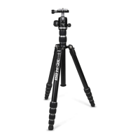
When you rst unbox your XC-M kit you will nd it in its most compact, storage state (see gure 1). Ideally,
this is how you will collapse and fold your tripod kit before travel and transport, when you need to minimize
its size.
Begin unfolding the legs from their transverse position. Grab ahold of two legs in their middles with one
hand while taking hold of the third leg near its rubber tip and leg locks with the other hand. Pull this third
leg away and open it a full 180 degrees. Once you have passed the 90-degree point in doing this you will
hear a series of 3 soft ‘clicks’. These clicks represent each of the 3 possible leg positions which can be used.
Once you have heard the third click you can stop opening the leg. Now reverse its direction and move it until
it stops. You have opened the leg to position #1 (see gure 2). Now repeat this process for the other 2 legs
while nding the most convenient place to hold the tripod in doing so. Once all 3 legs have been unfolded
into position #1 the tripod can be placed on a at surface like a oor or table.
You will notice the Quick Release or “QR plate” is pre-attached to the XC-M’s ball head. Leave it there for now
while you go through the next two sections to learn more about the XC-M’s operation.
A black fabric pouch is attached to the tripod’s yoke with a small, red carabiner. This is a Tool Kit (see gure 3)
which can be used for making adjustments to the tripod. You can choose to leave it attached to the tripod
for safe keeping or you can remove the Tool Kit. If you have purchased either the ProMaster 3580 XC-M
Shoulder Strap or the ProMaster 3587 Hipster & Strap Kit you can store these tools in the integrated pouches
featured in those accessories.
The nal part of our initial setup is to ensure the ball head is securely attached to the tripod. Sometimes it
can become loose after manufacturing and during shipping. With the tripod legs in position #1 raise the
Center Column Upper Section to its maximum height by rst loosening the Center Column Upper Lock. Slide
this section up and then tighten the Center Column Upper Lock to keep it in place. Now look at the under-
side of the Center Column Platform. You will see one small, silver-colored bolt know as a Grub Screw (see
gure 3). Open the tool kit and remove the Small Hex Key (see gure 3). Use it to ensure the Grub Screw is
tight. If the Grub Screw is loose, rst take ahold of the Ball Head and make sure its Panning Knob is tight.
Now rotate the Ball Head against the Center Column Platform to ensure it is tight. Then tighten the Grub
Screw to keep it in place.
INTRODUCTION
 Loading...