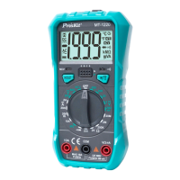
3.2.5 Current Measurement
The meter provides DC current measuring ranges as follows: 2mA,
20.00mA, 200.0mA and 10.00A.
Do not attempt a measurement on the current in a circuit, if
when the voltage between the open-circuit voltage and the
ground is over 250V. If the fuse is blown at the moment of
measurement, you are likely to damage the meter or get
yourself hurt.
To avoid any damage to the meter or equipment to be
measured, do not attempt a current measurement unless you
have examined the meter's protective tube. In attempting a
measurement, you should use the correct input sockets,
function positions and measuring ranges. When a test lead is
inserted into the current input socket, do not put the other end
of the test lead in parallel connection with any circuit.
Turn the rotary switch to the appropriate position.
Connect the test lead in black to COM input socket. Connect the test
lead in red to a mA input socket when the measured current is less
than 200mA; connect the test lead in red to a 10A input socket when
the measured current is 200mA~10A.
Disconnection of the circuit to be measured Connect the test lead
in black to the end of disconnected circuit (the voltage is lower)
and connect the test lead in red to the end of the disconnected
circuit (voltage is higher).
Connect the power to the circuit and capture the displayed reading.
If the display unit only shows "OL", it means the input is over the
selected measuring range. At this moment, turn the rotary switch
to a higher measuring range.
3.2.6 Temperature Measurement
Turn the rotary switch to the appropriate position (℃).
Insert the cathode of thermocouple’s cold end to " COM" jack and
anode to " V/Ω" terminal, put the working end on or in the tested
object, temperature value can be read on LCD in Celsius.
3.2.7 NCV Test (Non-contact Voltage Detection)
Turn the rotary switch to NCV position, and place the top of the meter
approach the conductor. If the meter detects the AC voltage, the
indicators for signal density (high, medium and low) will be on in
accordance with the detected density, while the beeper will sounds
 Loading...