EN | ENGLISH
19
MAINS SUPPLY
DANGER
Danger due to improper mains connection!
Incorrect mains connection can lead to persons or
property damage!
• Only operate the appliance at a socket with a
protective grounding conductor.
• If a new mains plug has to be connected, this
installation must only be carried out by a qualified
electrician according to the respective national
laws national regulations (any phase sequence for
three-phase current generators)!
• Mains plug, plug and socket must be checked at
regular intervals by an electrician!
Network Configuration
NOTE
The device may only be connected and operated on a
single-phase 2-wire
system with a grounded neutral conductor.
ATTENTION
Operating voltage – Mains voltage!
The operating voltage must correspond to the mains
voltage in order to avoid
damage to the device!
• Plug the mains plug of the disconnected device
into a suitable socket.
MAINTENANCE
NOTE
Proper, regular maintenance and cleaning of the device
is a prerequisite for the
maintenance of your warranty claims.
Daily maintenance
General visual inspection
Check the mains plug
Correct connection
Weekly maintenance
External relief from dust
Monthly maintenance
The device must be cleaned from the inside, depending
on the degree of use
Yearly maintenance
Repeat inspection according to standard IEC 60974-4
„Periodic inspection and testing during operation“.
Further information can be found in DIN VDE 0544-4.
CHECK
Procedure
Visual inspection
Electrical test
• Open-circuit voltage
• Isulating resistance
• Protective conductor resistance
Functional Test
Documentation
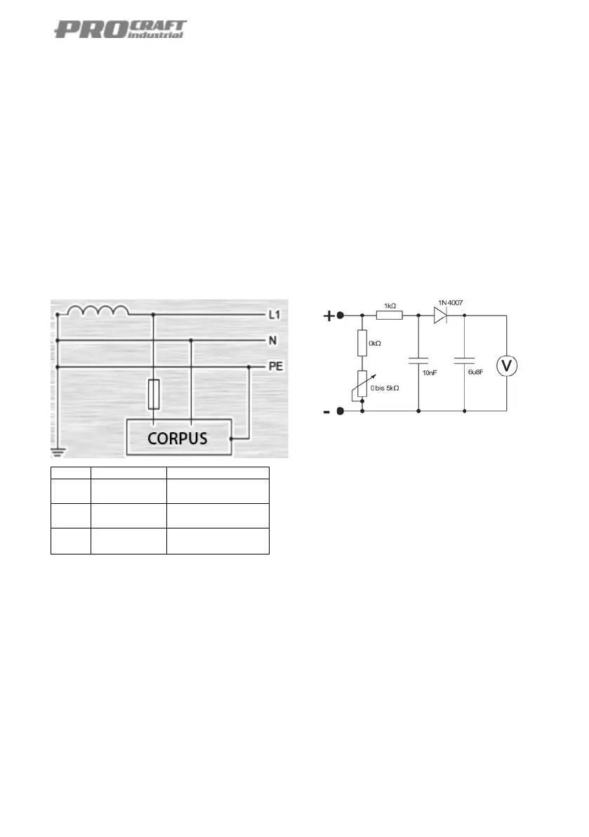
Measurement of open-circuit voltage
According to DIN EN 60974-1
The permissible tolerance of the components of the
circuit is ± 5%. The voltmeter has an internal resistance
of at least 1 M-Ohm and measures voltage values with a
measuring accuracy of ± 1% of the measuring range In
order to obtain the highest peak value – measured with
the load from 0.2 to 5.2 k-ohms – the potentiometer must
be adjusted from 0 to 5 k-ohms during the measurement.
Repeat the measurement with the opposite polarity. The
higher measured value applies.
Effective value are measured with a load of 5 ± 0.25 k-
ohm in the outer welding circuit with a device of the
accuracy class 1 for measuring true effective value.
Isulating resistance
Mains circuit against welding circuit and electronics 5 M-
ohm. Welding circuit and electronics against protective
conductor circuit (PE) 2.5 M-ohm.
Mains circuit against protective conductor circuit (PE)
2.5 M-ohm.
Protective conductor resistance
Is between the contact´s protective contact and
conductive conductive parts, such as housing screws,
housing covers, etc. during the measurement, the
connection cable must be moved along its entire length.
The resistance must not exceed 0.3 ohm for a mains
connection cable up to 5m length. For longer lines, the
permissible value is increased by 0.1 ohm 75 m line.
However, the maximum permissible value is 1 ohm.
 Loading...