Do you have a question about the PRONOVA SSM 6000 and is the answer not in the manual?
Covers hazards, unauthorized modifications, qualified personnel, explosive environments, and safe operation procedures.
Explains the SSM 6000's purpose, features, history, and additional functions for gas analysis.
Details the significance of measuring CH4, H2S, O2, CO2, and H2 in biogenic gases.
Lists measurement ranges, resolution, precision, and methods for CH4, H2S, O2, CO2, and H2.
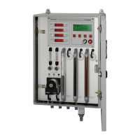
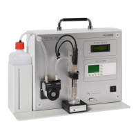
Describes front panel components including display, filters, flowmeters, and connections.
Explains the step-by-step process of gas measurement, including filtration and cooling.
Details LED/LC displays, status indicators, and operator controls for navigation and settings.
Describes the function, types, and replacement intervals for gas filters.
Explains how to measure and adjust gas flow rates using flowmeters and needle valves.
Describes the Peltier cooler's function, status LEDs, and error conditions.
Covers gas inlets/outlets, safety units, and detonation protection systems.
Explains the optional feature for selecting different measurement points.
Details the optional unit to prevent condensate accumulation during pauses.
Covers power supply, ports (1, 2), and communication interfaces (RS232, Profibus, CAN).
Covers installation location, ambient conditions, air pressure, and power supply specifications.
Details gas input/output conditions, corrosive gas handling, and calibration gas requirements.
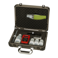
Lists included items and explains the rating plate and test certificate contents.
Provides physical dimensions and required clearance for installation.
Covers unpacking, assembly, electrical connections, and gas pipe connection procedures.
Explains the control panel buttons and how to navigate the analyzer's menus.
Describes methods for initiating measurements: manual, single, automatic, and external triggers.
Provides a visual flowchart of the analyzer's menu hierarchy for parameter settings.
Covers setting measurement intervals, alarm values, and performing single measurements.
Details selecting gas types, entering concentrations, and starting the calibration process.
Covers data logger, analog outputs, sensor data, operation modes, device ID, language, and date/time settings.
Describes the power-on sequence, warm-up phase, and entering setup mode.
Covers initial configuration of date/time, alarm values, measuring interval, and other settings.
Explains how to test analog output and other interface functionalities.
Details procedures for initial test runs with calibration gas and ambient air.
Describes transitioning to regular automated measurements and system checks.
Emphasizes calibration importance and details setup requirements and calibration gases.
Explains how to record the actual condition and check sensor signals prior to calibration.
Outlines the step-by-step process for calibrating the device including gas selection and setup.
Describes performing check measurements and resuming normal operations after calibration.
Describes monitoring and adjusting gas flow rates at regular intervals.
Covers cleaning and replacing the E460-3 safety unit due to potential clogging.
Details the types of gas filters and their recommended replacement intervals.
Covers changing the housing filter and the recommended annual calibration schedule.
Explains status LEDs and alarm messages for gas type limit violations.
Guides users on diagnosing and resolving issues with incorrect or implausible readings.
Addresses problems related to low or lacking measuring-gas flow and their causes.
Describes error conditions for the measuring gas cooler and potential causes.
Lists detailed performance parameters, dimensions, and operating conditions for the SSM 6000.
Lists consumable components, filters, and spare parts with article numbers.
Provides a blank form for recording calibration and check measurement data.
Includes EC compliance statements and relevant directives for the device.
Details pinouts and specifications for PORT 1 and PORT 2 connection cables.
Shows wiring schematics and connector layouts for analyzer versions A and B.
Provides an overview of the Profibus DP slave interface for the SSM6000.
Covers bus cable properties, shielding, connector types, and termination requirements.
Explains parameter data, configuration data, cyclic, and acyclic data exchange protocols.
Details how to set the Profibus device address and the device ID number.
Provides details from the GSD file for integrating the SSM6000 into a Profibus network.
| Brand | PRONOVA |
|---|---|
| Model | SSM 6000 |
| Category | Measuring Instruments |
| Language | English |