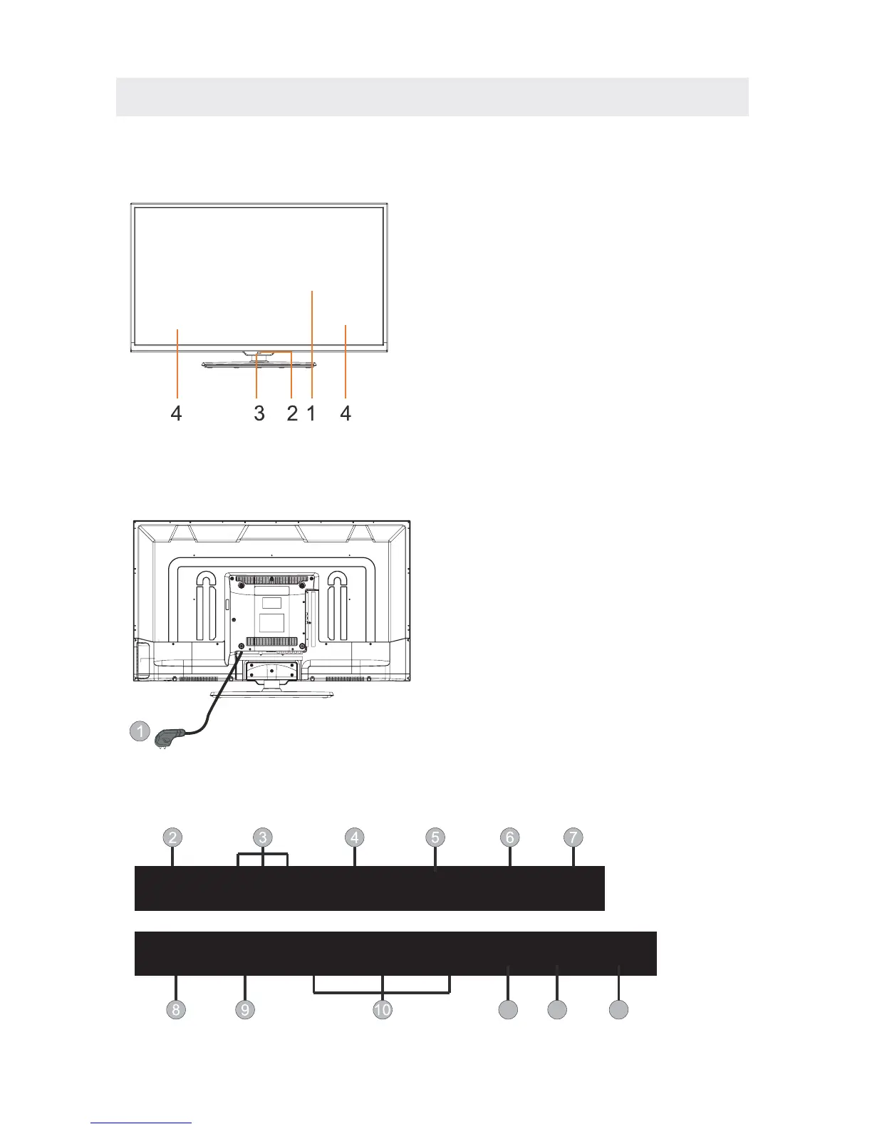
CONTROL REFERENCE GUIDE
FRONT VIEW
7
BACK VIEW
1.Color Screen
2.Remote Sensor
Do not block this sensor or the
remote control will not work.
3.Standby Indicator
Indicates whether the unit is ON
or in STANDBY (OFF) mode.
Light in red: The unit is in STANDBY.
Light in blue:The unit is turned ON.
4. Speakers
Video
R
L
SCART
VGA RF
YPbPr
Head
Phone
HDMI1 HDMI2
HDMI3
CI COAX
USB
1.Power Cord.
2.Video:Connect the Video output jack
of DVD or VCR.
3.R/L AUDIO:Connect the Video/YPbPr
AUDIO output jack of DVD.
4.SCART:Connect the SCART jack of VCR
or DVD.
5.PC AUDIO: Connect the Audio output
jack of PC.
6.VGA:
RF IN: Connect the antenna.
8.YPbPr:Component in jack.
9.Headphone: Connect the earphone.
10.HDMI1/2/3: Connect the HDMI output
jack of DVD.
11.CI:Connect to the CI card.
12.USB: Connect to portable usb device.
13.Coax: Coax output.
Connect a computer to these jacks.
7.
PC
Audio
11 12 13