- 20 -
Moving the turning tool
(longitudinal turning and lateral turning)
Apart from the quick adjustment of the support and the automatic
feed, the turning tool can be moved in 3 different ways.
A
. Movement with the leadscrew (longitudinal turning)
1. Disengage leadscrew (turn leadscrew switch 2 (Fig. 2) to
the left).
2. Engage support (push lever 3 (Fig. 3) downwards).
3. Move support using the handwheel 10 (Fig. 1).
1
turn = 1.5 mm
B. Movement of the top slide (longitudinal turning)
1. If required, clamp the support (tighten screw 2 (Fig. 3)).
2. Move top slide with handwheel 4.
1 turn = 1.0 mm.
C. Moving the cross-slide (face turning)
1. If required, clamp the support (tighten screw 2).
2. Move cross-slide with handwheel 5.
1 turn = 1 mm feed = 2 mm change in diameter.
Determining the correct spindle speed
The choice of the correct cutting speed is a decisive factor in
obtaining good results. In the case of longitudinal turning, this is
the peripheral speed of the workpiece. The table on the gearbox
of the machine provides directions for the choice of the correct
cutting speed.
When the cutting speed “Vc” and the workpiece diameter “D” are
known, the required spindle speed „n„ can be calculated as fol-
lows:
n = V
c
x 1000/ (D x 3.14)
Example: An aluminium workpiece with a diameter of 30 mm is to
be turned. The required cutting speed according to the table is
100 – 180 m/min. Thus: 132 m/min.
n = 132 x 1000/ (30 x 3.14) = 1400 rpm
This result can also be read directly from the table on the gear-
box.
Setting the spindle speeds
One way of changing the spindle speed is by switching the motor
speed (stepper switch 1, Fig. 4). This halves or doubles the
speed. Another way of changing the speed is by changing the
belt transmission.
1. Switch off the machine at the main switch 2 and open gearbox
3 with the Allen key.
2
. Loosen clamping screw 1 (Fig. 5) by half a turn.
3
. Turn screw 3 anti-clockwise using Allen key 2. This releases
the intermediate belt pulley 4.
4. Then change the belts as shown in Fig. 6.
5
. Remove Allen key 2 and tighten clamping screw 1.
6. Close gearbox 3 (Fig. 4).
N
ote:
I
t is possible that the motor will not always start when the multiple
contact switch is set to stage II. In this case, start by setting the
switch to I first and then to stage II.
Selecting the turning tool
There are several different types of turning tool. There follows a
brief explanation (see Fig. 7):
Roughing tools (1) are used to cut away as much material as
possible in a short time (without regard to the finish of the surface
of the workpiece).
Smoothing tools or thread chasers (2) are used to achieve a
smooth surface.
Right (3) and left side tools are used for longitudinal and face
turning and to turn out acute angles in a right or left hand working
direction.
Part-off tools (4) are used to start grooves and to cut off work-
pieces.
Threading tools (5) to cut external threads.
Internal turning tools (6) are used for turning out.
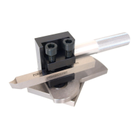
Inserting the turning tool in the tool
holder
The basic equipment of the PD 400 includes a multiple tool hold-
er (Fig. 8) consisting of tool holder block 1 and two tool holder
elements 2. For good working results, it is essential for the tool to
be set precisely to „the middle„ and that the turning tool is held
short to prevent vibration.
1. Place turning tool 3 in tool holder element 2. Tighten the two
screws 4 securely.
2. Place tool holder element in tool holder block 1. Adjust the
height of the turning tool via nut 5 and lock via nut 6. Adjust the
height of the blade to that of the centrepoint of the tailstock.
3. Clamp tool holder element with screw 7.
Note:
The entire holder block can be swivelled by loosening screw 8.
Example of longitudinal turning
Longitudinal turning designates the turning of a cylindrical work-
piece parallel to the turning axis. The following paragraph
explains work with the lathe to the beginner using the example of
longitudinal turning.
Clamp a short workpiece in the lathe chuck as described above
(remove the key from the chuck).
 Loading...