- 11 -
5. Unscrew screw 1 and insert milling head 2 (Fig. 7 a) into
the opening of flange 3. Reinsert screw 1 and tighten.
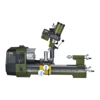
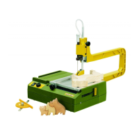
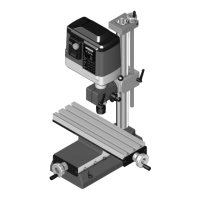
3.2 Mounting the milling cutter on the compound
table (Fig. 7 and Fig. 7a)
Note:
Safe and precise operation is only possible if the machine is
properly fastened to a stable work surface.
1
. Attach compound-type table to work surface using 4
screws 1 (M4, not included) (Fig. 8).
2. When working in conjunction with the PROXXON
PF 230 milling machine, insert pillar in flange and clamp
u
sing screws 2.
3. Unscrew screw 1 and insert milling head 2 (Fig. 7 a) into
the opening of flange 3. Reinsert screw 1 and tighten.
4 Working with the milling cutter
Attention:
Before carrying out any adjustment work, switch off the
device and disconnect the plug to prevent inadvertent
starting up!
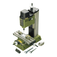
4.1 Height adjustment of spindle (Fig. 8):
The spindle of the PF/FF 250/BL can be adjusted in height in
2 ways:
1. With handwheel 1
2. With drilling lever 2
4.1.1 Height adjustment with the handwheel
1. Release clamping screw 3 (Fig. 9).
2. Adjust the desired height with the handwheel 1 (1 revo-
lution corresponds to 1mm feed).
3. Re-tighten the clamping screw 3
4.1.2 Working with the drilling lever
The drilling lever is not only useful for drilling holes, it can
also be used with a defined infeed adjustment such as with a
limit stop.
4.1.2.1 Easy drilling with the drilling lever:
1. Ensure that the screw 6 at scale ring 6 is loosened.
2. Release toggle screw 4
3. Swivel the drilling lever 2 to place the quill in the
required position. The quill is spring-loaded and returns
automatically to its top position after machining.
To read the machining depth at the scale of scale ring 5 while
machining, you must set it to zero first. This is quite easy:
1. Release the screw 6 at the scale ring.
2. Press down the drilling lever 2 until the bits and cutters
lightly touch the surface of the work piece.
3. Set the scale of the scale ring 5 to “0” and tighten the
screw 6.
When operating the drilling lever, the machining depth can
now be read on the scale.
4.1.2.2 Drilling with limit stop function:
I
f you prefer to work with an exactly defined machining depth,
proceed as follows:
1
. Release the screw 6 at the scale ring.
2
. With the machine switched off, set down the bits and
cutters very lightly on the surface of the work piece.
3. Set the required machining depth with the scale ring at
t
he marking on the machine.
4. Tighten screw 6.
When operating the drilling lever, the movement of the
spindle is now stopped when the set value is reached: drill
holes can now be drilled with exactly the same same depth,
for example.
Caution!
Please note that toggle screw 4 must always be tightened if
machining regularly, i.e. without the drilling lever!
4.2 Spindle fine feed Art. No. 24140 (Fig. 9)
When using this accessory, there is the option of effecting
spindle feed via the drill lever or by turning the handwheel 1
(Fig. 9).
Fitting the fine feed is simple:
1. Insert the shaft on the fine feed into the drill hole for the
drill lever shaft on the milling cutter. During assembly, it
is essential to observe the following: The “spring” on
the fine feed 2 fits into the slot on the drill lever shaft 3.
2. Align the fine feed and secure it with the screw
provided.
3. You can now switch the fine feed on or off with the cou-
pling shaft. To switch on, press your finger on the shaft
(4) and turn the handwheel at the same time.
4. The spring clicks into position in the slot. To switch off
the fine feed, simply pull the coupling out again.
4.2.1 Moveable scaling ring:
The moveable scaling ring 5 can be set to “0”. In this way,
you can precisely set the desired feed from any position. A
rotation of the handwheel corresponds to a feed of 1.5mm,
the distance between two large scale divisions is 0.1 mm.
5 Swivelling the milling spindle
5.1.1 Swivelling the milling spindle around the
vertical axis (Z axis, Fig. 5)
The entire milling spindle can be swivelled around two axes.
To swivel around the vertical axis (Z axis), loosen screw 2
(Fig. 5) and turn the column completely to the required posi-
tion. Then re-tighten the screw.
 Loading...