3
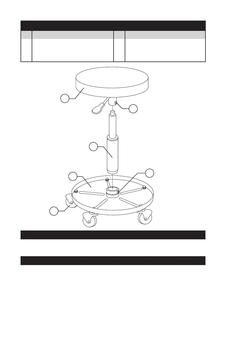
1. Loosen both Fasteners (2).
2. Make sure the tray is on a rm surface with the wheels down. Insert the Pneumatic
Cylinder (3) into the Tool Tray hole (4). The larger end of the Pneumatic Cylinder is
the end that inserts into the tool tray hole. It might be necessary to seat the Pneumatic
Cylinder. Do this by holding a block of wood over the top of the Pneumatic Cylinder and
gently tapping with a hammer to seat the Pneumatic Cylinder. NOTE: It might be easier
to position the Tool Tray, wheels down, on the grass or a surface that is not smooth.
3. Attach the Seat (1) to the top of the Pneumatic Cylinder (3).
4. Make sure both Fasteners are tightened (2). NOTE: It is recommended you take the time
to make sure that the Caster Wheels (5) are tight.
1
3
2
2
4
5
ASSEMBLY INSTRUCTIONS
CONTENTS
1 Padded Seat/Lifting Lever .. 1
2 Fasteners ............................ 2
3 Pneumatic Cylinder ............. 1
4 Tool Tray ............................. 1
5 Casters (attached) ..............5
No. Description Qty. No. Description Qty.
TOOLS REQUIRED
1. Adjustable wrench
2. Slotted screwdriver
3. Hammer and block of wood or
rubber mallet