CP10 Instruction Manual for Power Supplies
CP10 Bedienungsanleitung für Stromversorgungen
Terminals and Wiring
Use appropriate copper cables that are designed for a minimum operating temperature of:
60°C for ambient temperatures up to 45°C,
75°C for ambient temperatures up to 60°C and
90°C for ambient temperatures up to 70°C.
Follow national installation codes and regulations! Ensure that all strands of a stranded wire enter
the terminal connection! Ferrules are allowed. Unused terminal must be closed.
Input / Output Input / Output Signals
CP10.xxx CP10.xxx-S1 All units
Typ Screw term. Spring-clamp Spring-clamp term.
Solid wire max. 6mm
2
max. 6mm
2
max. 1.5mm
2
Stranded wire max. 4mm
2
max. 4mm
2
max. 1.5mm
2
American wire gauge AWG 20-10 AWG 20-10 AWG 28-16
Max. wire diameter (incl. ferrules) 2.8mm 2.8mm 1.6mm
Wire stripping length 7mm / 0.28inch 10mm / 0.4inch 7mm / 0.28inch
Tightening torque 1Nm / 9lb.inch - -
Anschlussklemmen und Verdrahtung
Verwenden Sie geeignete Kupferkabel, die mindestens für:
60°C bei einer Umgebungstemperatur bis zu 45°C,
75°C bei einer Umgebungstemperatur bis zu 60°C und
90°C bei einer Umgebungstemperatur bis zu 70°C zugelassen sind.
Aderendhülsen sind erlaubt. Nationale Bestimmungen und Installationsvorschriften beachten!
Achten, dass keine einzelnen Drähte von Litzen abstehen. Nichtbenutzte Klemmen schließen.
Ein- / Ausgang Ein- / Ausgang Signale
CP10.xxx CP10.xxx-S1 Alle Geräte
Klemmentyp Schraubanschluss Federkraftklemme Federkraftklemme
Starrdraht max. 6mm
2
max. 6mm
2
max. 1,5mm
2
Litze max. 4mm
2
max. 4mm
2
max. 1,5mm
2
AWG AWG 20-10 AWG 20-10 AWG 28-16
Max. Durchmesser (inkl. Hülsen) 2,8mm 2,8mm 1,6mm
Abisolierlänge 7mm / 0,28inch 10mm / 0,4inch 7mm / 0,28inch
Anzugsdrehmoment 1Nm / 9lb.inch - -
Isolation and Dielectric Strength (see Fig. 2)
The output voltage is floating and separated from the input according to SELV (IEC/EN 60950-1)
and PELV (EN 60204-1, EN 50178; IEC 62477-1, IEC 60364-4-41) requirements. Type and
factory tests are conducted by the manufacturer. Field tests may be conducted in the field using
the appropriate test equipment which applies the voltage with a slow ramp (2s up and 2s down).
Connect all phase-terminals together as well as all output poles before the test is conducted.
When testing, set the cut-off current settings to the value in the table below.
A B C D
Type Test (60s) 2500Vac 4000Vac 1000Vac 500Vac
Factory Test (5s) 2500Vac 2500Vac 500Vac 500Vac
Field Test (5s) 2000Vac 2000Vac 500Vac 500Vac
Cut-off current setting >10mA >10mA >20mA >1mA
Galvanische Trennung und Isolationsfestigkeit (siehe Bild 2)
Die Ausgangsspannung hat keinen Bezug zur Erde oder Schutzleiter und ist zum Eingang nach
den SELV (IEC/EN 60950-1) und PELV (EN 60204-1, EN 50178, IEC 62477-1, IEC 60364-4-41)
Standards getrennt. Typ- und Stückprüfungen werden beim Hersteller durchgeführt. Wieder-
holungsprüfungen dürfen mittels geeigneten Prüfgenerators mit langsam (2s) ansteigenden und
abfallenden Spannungsrampen in der Anwendung erfolgen. Vor den Tests sind alle Phasen wie
auch alle Ausgangspole miteinander zu verbinden. Während der Tests darf die Strom-
Abschaltschwelle nicht kleiner als der in der Liste angegebene Wert sein.
A B C D
Typprüfung (60s) 2500Vac 4000Vac 1000Vac 500Vac
Stückprüfung (5s) 2500Vac 2500Vac 500Vac 500Vac
Wiederholungsprüfung (5s) 2000Vac 2000Vac 500Vac 500Vac
Strom- Abschaltschwelle >10mA >10mA >20mA >1mA
Hiccup
PLUS
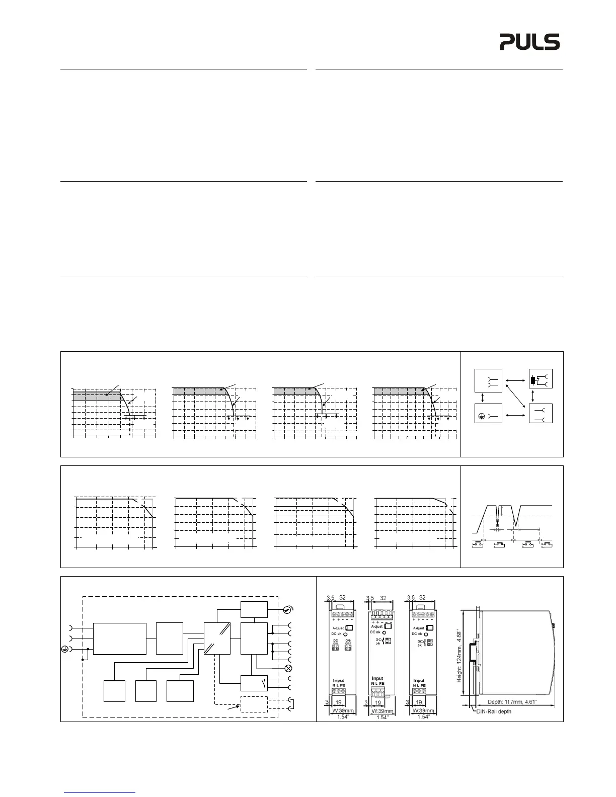
Overload Characteristic (see figures 1)
The unit is overload, no-load, short-circuit proof. The output current is electronically controlled.
During an overcurrent situation, the output voltage will be reduced after a defined time. If the
voltage falls below 6.5V (12V unit), 13V (24V units), 20V (36 V unit) or 26V (48V unit), the unit
switches to the Hiccup
PLUS
mode. In this mode, the output switches off followed by a restart
attempt after 18s for 2s. This cycle is repeated as long as the overload or short circuit exists. If the
overload or short circuit has been cleared, the device will operate normally.
Hiccup
PLUS
Überlastverhalten (siehe Bilder 1)
Die Geräte sind leerlauf-, überlast- und kurzschlussfest. Der Ausgangsstrom ist elektronisch
überwacht. Während einer Überstromsituation wird nach einer bestimmten Zeit die
Ausgangsspannung reduziert. Fällt die Spannung unter 6.5V (12V Gerät), 13V (24V Geräte), 20V
(36V Gerät) oder 26V (48V Gerät), schaltet das Gerät in den Hiccup
PLUS
Modus. In diesen Modus
schaltet das Gerät ab und macht nach 18s einen Startversuch mit einer Dauer von 2s. Der
Vorgang wiederholt sich solange, bis die Überlast oder der Kurzschluss entfernt ist. Nach
entfernen der Überlast oder des Kurzschlusses schaltet das Gerät wieder in den Normalbetrieb.
Fig. 1/ Bild 1 Output Characteristic / Ausgangskennlinie, typ.
CP10.121 CP10.241, CP10.241-S1, CP10.242 CP10.361 CP10.481
Fig. 2 / Bild 2
Insulation / Isolation
Output Voltage
0
020
2
4
6
16V
8
10
12
35
62 4 8 12 14
Adjustment
Range
Output Current
Continuous
current
Hiccup
PLUS
mode
Output Voltage
0
06
8
16
24
56V
32
40
48
10A41 2 5 783 9
Adjustment
Range
Output Current
Continuous
current
Hiccup
PLUS
mode
A
D
C
B
B
*)
L
Input DC-ok
13
14
Earth, PE
Output
15/16
+/-
Shut-down
N
B*) When testing input to DC-OK ensure that
the max. voltage between DC-OK and the
output is not exceeded. We recommend
connecting DC-OK pins and the output pins
together when performing the test.
Fig. 3/ Bild 3 Output Derating / Leistungsrücknahme
CP10.121 CP10.241, CP10.241-S1, CP10.242 CP10.361 CP10.481
Fig. 4 / Bild 4
DC-OK
Allowed Output Current at 12V
0
-25 0 20 40
70°C
4A
8A
12A
16A
20A
60
A
Ambient Temperature
A...85 to 264Vac, continuous
B... short term
B
Allowed Output Current at 24V
0
-25 0 20 40
70°C
2A
4A
6A
8A
10A
12A
60
A
Ambient Temperature
A...85 to 264Vac, continuous
B... short term
B
Allowed Output Current at 36V
0
-25 0 20 40
70°C
2A
4A
6.7A
8A
60
5A
6A
A
Ambient Temperature
A...85 to 264Vac, continuous
B... short term
B
Allowed Output Current at 48V
0
-25 0 20 40
70°C
1A
2A
3A
4A
5A
6A
60
A
Ambient Temperature
A...90 to 264Vac, continuous
B... short term
B
100ms
0.9* V
ADJ
<
1ms
10%
open
V
OUT
= V
ADJ
openclosed closed
>
1ms
Fig. 5 / Bild 5 Functional Diagram / Funktionsschaltbild Fig. 6 / Bild 6 Mechanical dimensions / Abmessungen
CP10.121 CP10.241-S1 other units all units
+
+
-
-
Output Over-
Voltage
Protection
PFC
Converter
Output
Voltage
Regulator
Power
Converter
Output
Filter
Output
Power
Manager
Temper-
ature
Shut-
down
Input Fuse
Input Filter
Input Rectifier
Inrush Current Limiter
V
OUT
L
N
DC-ok
Contact
DC-ok
LED
DC-ok
Relay
-
Shut-down
13
14
ON/
OFF
15
16
Only for CP10.121
PU-410.012.00-10B (2016-02)
The information in this document is believed to be accurate and reliable and may change without notice.
 Loading...