Live, Neutral and Earth Outputs: Terminal blocks are provided for
connection to your lamps etc. Two terminals are provided for each
live output.
Important: with 3 phase delta supply use the correct neutral terminal
block - see Front Panel printing for channel numbers.
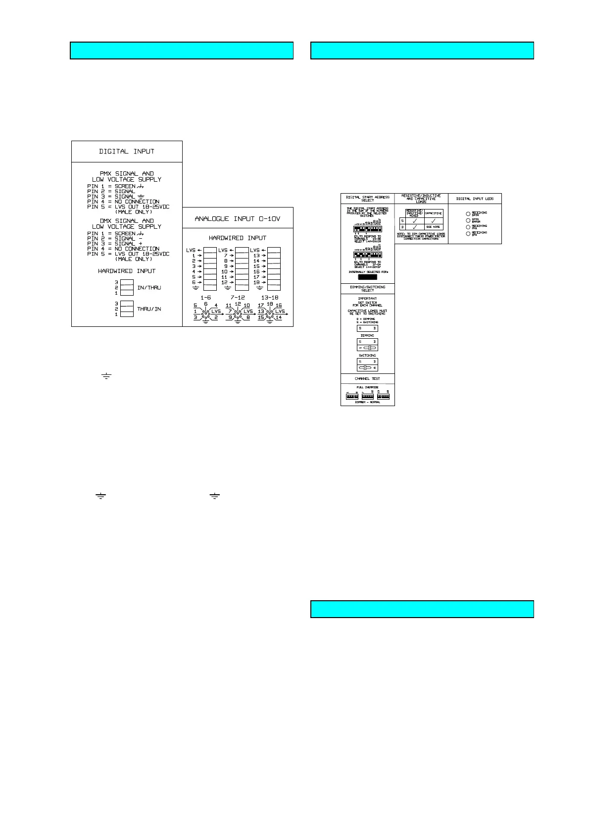
SIGNAL CONNECTIONS
may be made by either using the sockets
provided (8 pin DIN / 5 pin XLR) or by hardwiring.
Analogue Control Signals: One 8 pin DIN socket is provided for
each six channels. The pin connections are:
Pin 1 =
Low Voltage Supply Out Pin 5 = Channel 3/ 9/15
Pin 2 =
Chassis Earth Pin 6 = Channel 4/10/16
Pin 3 =
Channel 1/7/13 Pin 7 = Channel 5/11/17
Pin 4 =
Channel 2/8/14 Pin 8 = Channel 6/12/18
For hardwiring, the connections to the terminal blocks are indicated
on the Front Panel and the PCB.
Digital Control Signals: Two 5 pin XLR sockets (in / thru) and
two 3 way terminal blocks are provided for the digital inputs. The pin
connections are:
For hardwiring, the connections to the terminal blocks are indicated
on the Front Panel and the PCB.
Note:
Pins 4 and 5 are occasionally used by other manufacturers for
data. We recommend the use of 2 core plus screen cable, leaving
pins 4 and 5 open circuit, to connect to this type of equipment.
However, the Low Voltage Supply on pin 5 of the male XLR is
limited to cause no harm to such equipment.
Technical Details:
0V = Off (Dimming and Switching Datapaks)
>+3V = Full On (Switching Datapaks)
+10V = Full On (Dimming Datapaks)
The input impedance is 100k ohms.
The Low Voltage Supply (LVS) available for a Controller from pin
1 of the DIN sockets or pin 5 of the XLR male chassis connector is
+18...25VDC at up to 120mA.
Analogue control cables do not need to be screened as the inputs
of the Datapak are filtered against hum and interference.
The cables may be as long as necessary and the minimum size of
their conductors is limited only by considerations of mechanical
strength.
The internal controls and indicators are only to be operated by
suitably skilled and competent persons.
Digital Start Address Select and Test Switches: The digital start
address is the sum of the numbers produced by the selected
switches - see examples on Front Panel. The Test Switch provides
a block of three channels moving through the Datapak channels.
Digital Input LEDs (Red): There are four LEDs provided, the RX
LED shows when data is being received, the ERR LED indicates an
ERRor in the received data, and the PMX (Pulsar MultipleX using
RS232/423) and DMX LEDs show the type of data being received by
the Datapak. The software automatically recognises both PMX and
DMX.
Normal/Full-On Channel Test Switches: One per channel. The
switches should be in the "Norm" position for control from a desk.
Use the "Full On" position for testing and diagnostics without having
to connect a desk.
Output Monitor LEDs (Green): One per channel, indicating it's
status before the output circuitry (triac, choke etc.). Thus it may be
used in conjunction with the Output Monitor Neon to indicate the
location of a possible fault. If it fails to light when the appropriate
Channel Test Switch is set to full then there will be a fault in the
electronics or the input may be shorted. If it lights but the Output
Monitor Neon does not then there will be a fault in the output
circuitry.
Resistive / Inductive Loads: All Datapak III models will work with a
resistive, inductive, or mixed load.
Dimming / Switching Datapaks ONLY
Dimming / Switching Switches may be set to D (Dimming) or
S (Switching) for each channel.
Capacitive Loads
may be Switched but not Dimmed.
If a channel fails to light, a fuse may have blown. These fuses
normally only blow if the output is overloaded. Do not exceed the
maximum load stated on the Front Panel per channel and do not
short circuit the outputs. We recommend that you check your
lighting equipment regularly for damaged wiring, loose connections
and potential short circuits. If a fuse blows, locate and rectify the
fault before replacing it.
Channel Fuses: If a channel fuse blows, isolate the Datapak from
the supply, then locate and rectify the fault in the lighting system
before changing it. Important - Only the type of fuse specified on
the front panel may be used - other types will not protect the triacs.
Electronics Fuse: Failure indicates an internal fault and servicing by
a qualified engineer will be required.
PMX SIGNAL AND LV SUPPLY DMX SIGNAL AND LV SUPPLY
Pin 1 =
Chassis Earth - Screen Pin 1 =
Chassis Earth - Screen
Pin 2 =
Signal Pin 2 = Signal -
Pin 3 =
Signal Earth Pin 3 = Signal +
Pin 4 =
no connection Pin 4 = no connection
Pin 5 = Low Voltage Supply Out Pin 5 = Low Voltage Supply Out
male XLR only male XLR only
CONNECTIONS cont.
INTERNAL CONTROLS AND INDICATORS
FUSES
 Loading...