Wiring Conventions
Wiring Conventions Wiring Conventions
Wiring Conventions used
used used
used in P
in Pin P
in PULSE Power Amplifiers
ULSE Power AmplifiersULSE Power Amplifiers
ULSE Power Amplifiers
Signal (Input)
Signal (Input)Signal (Input)
Signal (Input)
Phono/RCA (unbalanced); Tip=Signal Positive, Sleeve=Signal Ground.
XLR (balanced); Pin1=Signal Ground, Pin2=Signal Positive, Pin3=Signal Negative.
6.35mm (1/4”) Jack (balanced); Tip=Signal Positive, Ring=Signal Negative, Sleeve=Signal Ground.
6.35mm (1/4”) Jack (unbalanced); Tip=Signal Positive, Sleeve=Signal Ground.
Speaker (Output)
Speaker (Output)Speaker (Output)
Speaker (Output)
Speakon; 1+=Speaker Positive. 1-=Speaker Negative.
Binding Posts; Red=Speaker Positive. Black= Speaker Negative.
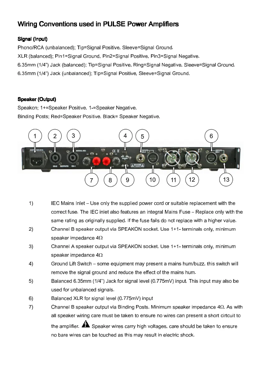
1)
IEC Mains Inlet – Use only the supplied power cord or suitable replacement with the
correct fuse. The IEC inlet also features an integral Mains Fuse – Replace only with the
same rating as originally supplied. If the fuse fails do not replace with a higher value.
2)
Channel B speaker output via SPEAKON socket. Use 1+1- terminals only, minimum
speaker impedance 4Ω
3)
Channel A speaker output via SPEAKON socket. Use 1+1- terminals only, minimum
speaker impedance 4Ω
4)
Ground Lift Switch – some equipment may present a mains hum/buzz, this switch will
remove the signal ground and reduce the effect of the mains hum.
5)
Balanced 6.35mm (1/4”) Jack for signal level (0.775mV) input. This input may also be
used for unbalanced signals.
6)
Balanced XLR for signal level (0.775mV) input
7)
Channel B speaker output via Binding Posts. Minimum speaker impedance 4Ω. As with
all speaker wiring care must be taken to ensure no wires can present a short cirtcuit to
the amplifier. Speaker wires carry high voltages, care should be taken to ensure
no bare wires can be touched as this may result in electric shock.
 Loading...