4.5 ALM, DST LED (5mm Yellow LEDs)
SYNC (5mm Green LED)
Solder the three LEDs as shown below. The longer LED Lead goes
in the hole with a circle marking.
4.6 Sync Conn (Vertical jack socket)
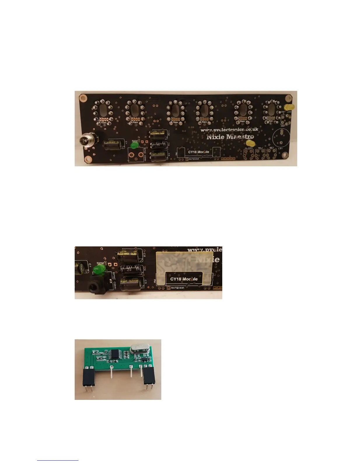
4.7 Insulating Sheet
If you will not be using the CY18 Receiver module, you can omit
steps 4.7 to 4.8.
Peel off the white paper backing and attach the insulation as shown
below.
4.8 CY18 Module and Connectors
Push the two connectors onto the end pins of the CY18 receiver Module.