www.PyleUSA.com4 www.PyleUSA.com 5
11. Power switch for the assistance light: Power ON/OFF the light according to
the switch position.
12. Assistance light connector: This is BNC connector, it can supply 12V/0.5A
power, use a gooseneck light to connect.
13. Always Power Outlet: Assistant power outlet, connects to the AC input
directly, power always valid.
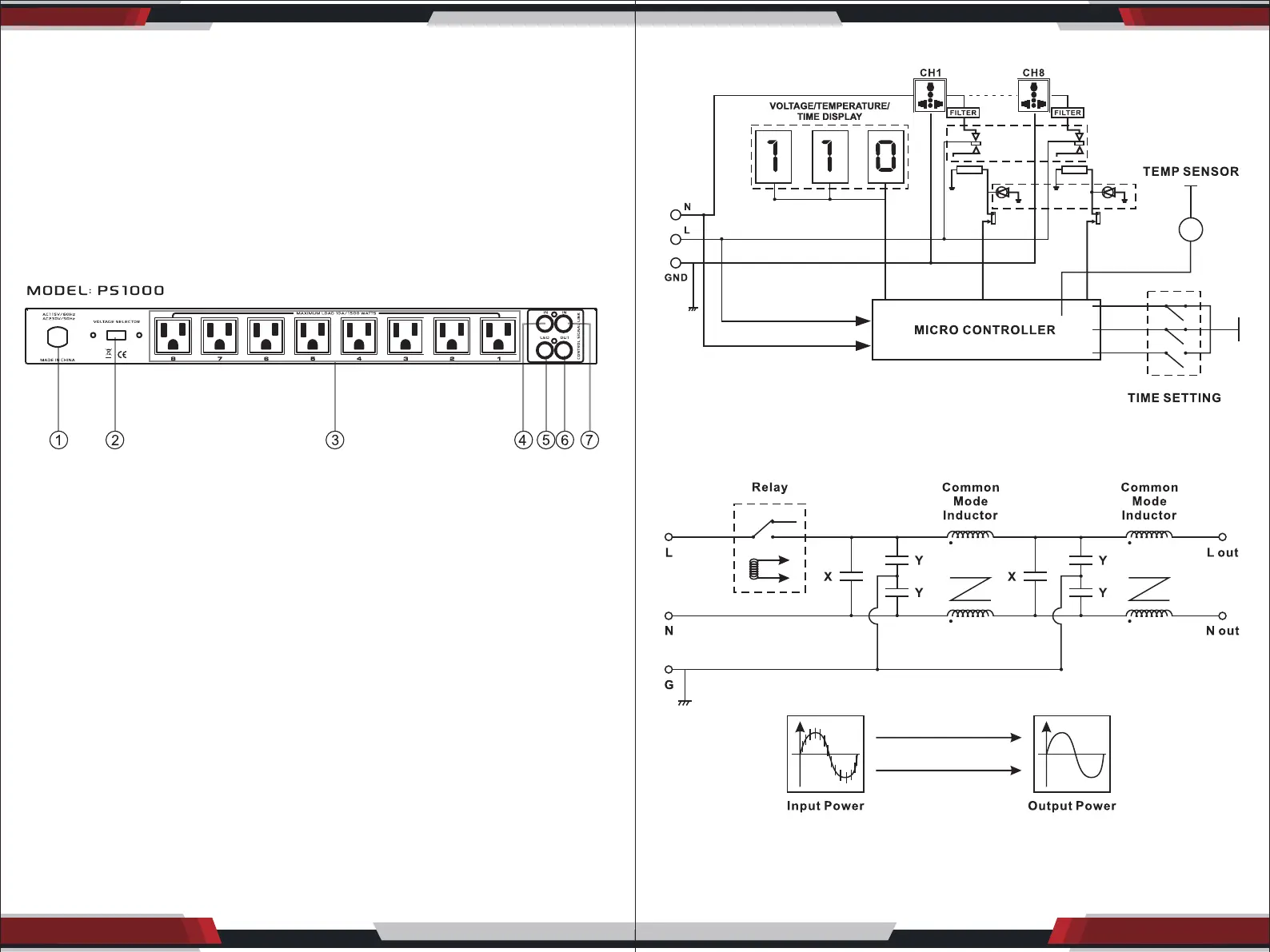
Rear Panel Introduction
1. Main power supply with standard American plug
2. Input Voltage Selective: Power Supply Switch at 115V/60Hz or 230V/50Hz
3. Outlets OUT1-OUT8: Power outlet can carry 15AMP (RMS) each outlet,
otherwise the unit is not safe.
4. Remote Control link: You can set a extra switch to replace the power switch
to achieve the long distance control.
5. LED for remote control: Indicates the unit status, use it with Remote control.
6. Link out: Many unit works via link, if you want to link next unit, the lower unit
should be connected here.
7. Link in: Many unit works via link, if you need to link up, then the upper unit
should be connected here.
BLOCK DIAGRAM
Filter Schematic Diagram