© 2005 Directed Electronics—all rights reserved
99
IIMMPPOORRTTAANNTT!!
Do not test tachometer wires with a test light or logic probe. The vehicle will be
damaged.
HHooww ttoo ffiinndd aa ttaacchhoommeetteerr wwiirree wwiitthh yyoouurr mmuullttiimmeetteerr::
1. Set to ACV or AC voltage (12V or 20V is fine).
2. Attach the (-) probe of the meter to chassis ground.
3. Start and run the vehicle.
4. Probe the wire you suspect of being the tachometer wire with the red probe of the meter.
5. If this is the correct wire the meter will fluctuate with the rpm of the motor and read between 1V and 6V.
In diesel vehicles it is necessary to interface with the wire that turns on the WAIT TO START light in the dash-
board. This wire illuminates the bulb until the vehicle’s glow plugs are properly heated. When the light goes out
the vehicle can be started. This wire is always available at the connector leading to the bulb in the dashboard.
It can also be found at the Engine Control Module (ECM) in many vehicles.
TToo tteesstt aanndd ddeetteerrmmiinnee tthhee ppoollaarriittyy ooff tthhiiss w
wiirree::
1. Set your multimeter to DCV or DC voltage (12 or 20V is fine).
2. Attach the (+) probe of the meter to (+)12V.
3. Probe the wire that you suspect leads to the bulb with the (-) probe of the meter.
4. Turn the ignition switch to the ON position.
5. If the meter indicates 12 volts until the light goes out you have isolated the correct wire and the wire's polar-
ity is negative (ground while the bulb is on).
6. If the meter reads zero volts until the light goes out and then reads 12 volts, you have isolated the correct
wire and the wire's polarity is positive.
wwiirriinngg ddiiaaggrraammss
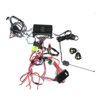
The primary harness supplied with this unit is the standard 12-pin harness used by Directed Electronics security
systems. Three wires in the plug are not used. The upgrade from this unit to a security system would simply
require unplugging and exchanging control units and connecting the necessary wires to the vehicle. The func-
tions of all the wires that are used in the primary harness are outlined in the following wiring diagram and the
wire connections are described in the wire connection guides.
pprriimmaarryy hhaarrnneessss ((HH11)) wwiirriinngg ddiiaaggrraamm
ffiinnddiinngg tthhee wwaaiitt--ttoo--ssttaarrtt bbuullbb wwiirree ffoorr ddiieesseellss
 Loading...