NOTE: This heater has a continuous fan-only feature. See
page 3 for details.
Installation of Recessed Back Box
in New Construction
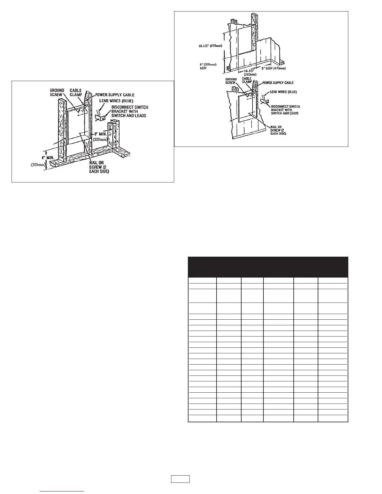
1. Mounting Back Box (See Figure 1).
a
. Place the back box between two 16" (406 mm) center-to-
center wall studs at the desired mounting height but no
closer than 8" (203 mm) to adjacent wall or floor.
Note: If wall studs are spaced greater than 16” on center, addi-
tional framing supports may be necessary.
b. Align back box such that the bottom and sides will be
flush with finished wall surface (top flange of back box
should protrude approximately 1/2" (12.7 mm) from fin-
ished wall surface).
c. Secure the back box in position with wood screws or nails
as shown in Figure 1.
2. Power Supply Wiring (See Figure 1)
NOTE: Wire compartment volume - 119in
3
(1950cm
3
).
a. Run a power supply cable into the knockout area in the
upper right hand corner of the back box. All wiring must be
in accordance with National and Local Electrical Codes.
Refer to Table 1 for correct wire size.
b. Remove disconnect switch bracket by loosening two
screws on the right side.
c. Install a cable clamp in the “knockout” in the top of the
back box.
d. Insert power supply cable through cable clamp, allowing at
least 6" (152mm) of leads to extend inside the back box.
Connect the blue lead wires of disconnect switch to the
supply wire leads using wire connectors (see wiring dia-
gram, pg. 3.)
e. Ground the back box by connecting the supply ground lead
wire to the green ground screw located in the inside top of
the back box.
f. Secure disconnect switch bracket in place by tightening
screws.
Installation of Recessed
Back Box in Existing Construction
1. Provide a wall opening 14-1/2" (362mm) wide by 18-1/2"
(470mm) high at the desired mounting height, but no closer
than 8" (203mm). (See Figure 2.)
Note: Locate so at least one side of opening is at wall stud.
2. Power Supply Wiring
NOTE: Wiring Compartment Volume - 119in
3
(1950cm
3
).
a. Run a power supply cable into the area above the top of the
wall opening. All wiring must be in accordance with National
and Local electrical codes. Refer to Table 1 for correct wire
size.
b. Remove disconnect switch bracket by loosening the two
screws on the right side.
c. Install a cable clamp in the “knockout” in the top of wall
back box.
d. Insert power supply cable through cable clamp, allowing
approximately 6" (152mm) of cable length to remain inside
the back box to facilitate connections.
3. Mounting Back Box
a. Place the back box into wall opening flush with finished
wall surface on bottom and sides of box. (Top flange of
backbox should protrude approximately 1/2" or 12.7mm
from finished wall surface).
b. Secure the back box in place with wood screws or nails.
4. Wiring Disconnect Switch
a. Connect the power supply wires to the blue wires of the
disconnect switch using wire connectors (see wiring dia-
gram, pg. 3)
b. Ground the back box connecting the supply ground lead
wire to the green ground screw located in the inside top of
the back box.
c. Secure disconnect switch bracket in place by tightening
screws.
Fig. 1: Locating Recessed Back Box in New Construction
Fig. 2: Locating Recessed Back Box in Existing Construction
2
B
ACK BOX
B
ACK BOX
TABLE 1
MMIINN.. SSUUPPPPLLYY
CATALOG WIRE
NUMBER VOLTS PHASE WATTS AMPS GAUGE
CWH3150 120 1 1500 12.5 12
CWH3180 120 1 1800 15.0 12
CWH3404* 240/208 1
4000/3000 16.7/14.5 10
2000/1500 8.3/7.2 12
CWH3407* 277/240 1
4000/3000 14.5/12.5 12
2000/1500 7.2/6.3 12
CWH3307* 277 1 3000/1500 10.8/5.4 14
CWH3408* 208 1 4000/2000 19.2/9.6 10
CWH34083 208 3 4000 11.1 14
CWH34043 240 3 4000 9.7 14
CWH3504 208/240 1 3600/4800 17.3/20.0 10
CWH3507 240/277 1 3600/4800 15.0/17.3 10
CWH3508 208 1 4800 23.1 10
CWH35083 208 3 4800 13.4 12
CWH35043 240 3 4800 11.6 14
CWH3203 347 1 2000 5.8 14
CWH3206 600 1 2000 3.3 14
CWH3153 347 1 1500 4.3 14
CWH3156 600 1 1500 2.5 14
CWH3303 347 1 3000 8.6 14
CWH3306 600 1 3000 5 14
CWH3403 347 1 4000 11.5 14
CWH3406 600 1 4000 6.7 14
CWH3503 347 1 4800 13.8 12
CWH3506 600 1 4800 8 14
* Factory wired for higher wattage. Field convertible to half wattage.