IMPORTANT!
QDX produces 5 W power output from a supply voltage of 9V or a little over. At 12 V QDX could
be producing 8 W power output which is likely to cause over-heating and perhaps failure of the
BS170 final transistors.
Operation of QDX at more than 6W power output is NOT RECOMMENDED.
If you wish to operate using a 12 V supply, you may use a two turn secondary winding on the
output transformer T1, so a 3:2 ratio instead of the 3:3 turns ratio documented in this manual.
Remember this when you come to the assembly step for preparing and installing the output
transformer T1. The “primary” is still 3 turns, with a tap half way at 1.5 turns. The secondary (no
tap) will now be only two turns.
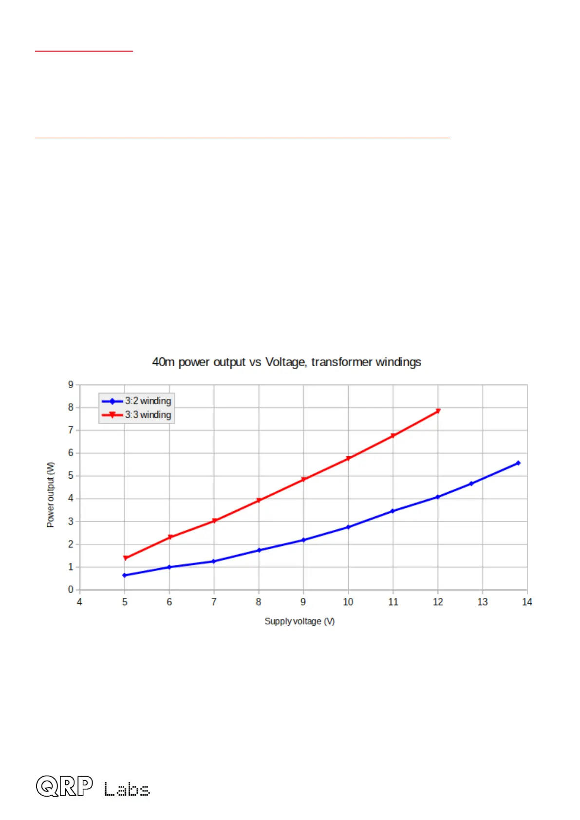
The chart below shows the measured power output vs supply voltage for the standard 3:3 winding
(Red line); at 12 V supply the output power of around 8 W is too high and likely to cause over-
heating or failure of the power amplifier transistors. If you wish to use a supply of 12 - 13 V the 3:2
winding style is more suitable and will produce 4 – 5 W output for 12 – 13 V supply. The graph
shows 40m but other bands are very similar.
4
 Loading...

