www.arrl.org QST March 2023 51
nique is beyond the scope of this review), this connector
can be used to insert the code for your unique wave-
form or to store and make available to a similar unit the
current waveform.
The front panel USB connector has a unique ability. It
can be used to store a BMP le of the display screen. It
also is a port used with several other RIGOL products.
Along the bottom of the panel are three BNC connec-
tors. The rst two are outputs for the two channels of
the generator. Above and in between these BNCs is a
channel select switch. To either side are two buttons
labeled CH1 (channel 1) and CH2 (channel 2). These
turn on the selected channel outputs.
The select switch selects either channel for entry. When
a channel is selected for output, it is highlighted at the
top of the screen. The select button routes the com-
mands to either channel 1 or 2.
A few of the internal stored waveforms are selected by
the top row of buttons. In the left row, the next button
down allows selection of various modulations, including
AM, PM, ASK, PSK, and PWM. Below it are various
sweep selections —
SINE, SQUARE, RAMP, and pro-
grammable.
Finally, the bottom row selects one of several internal
burst waveforms de ned with the same names as the
modulations. The three remaining buttons below the
SQUARE button are system controls. UTILITY allows
selection of various sync, polarity, and delay parameters
for a currently selected waveform.
STORE provides
selection of storage place (internal or on the USB ash
drive), and the
HELP button provides text explaining a
previously selected control. Depending on the button
selected, there may be one or several help screens for
the button. The return button exits help and returns you
to the previous screen. Both this help le and the le
downloaded from the QR noted before (http://support.
rigol.com/File/DC/DG1000Z_QuickGuide_CN&EN.
PDF) give you more front panel button explanation.
8 mega points (Mp) devoted to the waveform construc-
tion. Extra memory in some models increases this to
16 Mp. For some applications, the claimed stability of
the square wave generated is jitter of less than 300 ps
plus 5 ppm of the period — up to a 60 MHz frequency.
A word of caution: while just about all the numbers
quoted in this review are impressive, occasionally there
were con icts between various pages of the manufac-
turer’s posted material. Sometimes it was not apparent
which model was being quoted.
Check carefully that the material you download applies
to the model series in which you are interested. For
example, the SDG1000X series has a completely differ-
ent front panel than the SDG1000Z series. A “Z” series
unit is the one examined for this review.
Front Panel Controls and Ports
Almost every control and setting on the front panel has
an accuracy associated with it. Because this is a labora-
tory-type instrument, many of these numbers corre-
spond to the industrial standards to which the unit is
supposed to conform. The front panel layout (see the
lead photo for this unit) may look familiar, as it resem-
bles the front panel of several of the units reviewed in
this comparison.
To the right of the display is a set of ve soft keys —
their use is not xed but varies with the exact unit set-
tings. On the right is the now-familiar rotary knob. When
you want to change a value, the knob changes the digit
value (from 0 to 9), and the left and right arrow buttons
change the place of the digit selected. For example, for
“----7----,” the round knob varies the 7 and the left and
right arrow buttons below the knob select the position.
However, if you nd this place/digit system tedious (as
I did), the numerical keyboard gives you direct entry of a
number.
There are a few unique features of this panel. Below the
ve soft keys is a similar-colored key with an arrowhead
pointing down. For some settings, this key takes you to
a menu sub-setting. To the right of this key is a key with
a counterclockwise arrow. When the unit is in a sub-
menu, pressing this key will return you to the previous
menu. Not all settings have a controllable menu/sub-
menu feature.
On the lower right is the power
ON/OFF switch with the
standard industry markings — the small 0 setting indi-
cates off, and the small horizontal bar indicates on. To
the right is a surprise — a USB socket. Because the
unit can be programmed with your unique waveform (a
full description of the programming language and tech-
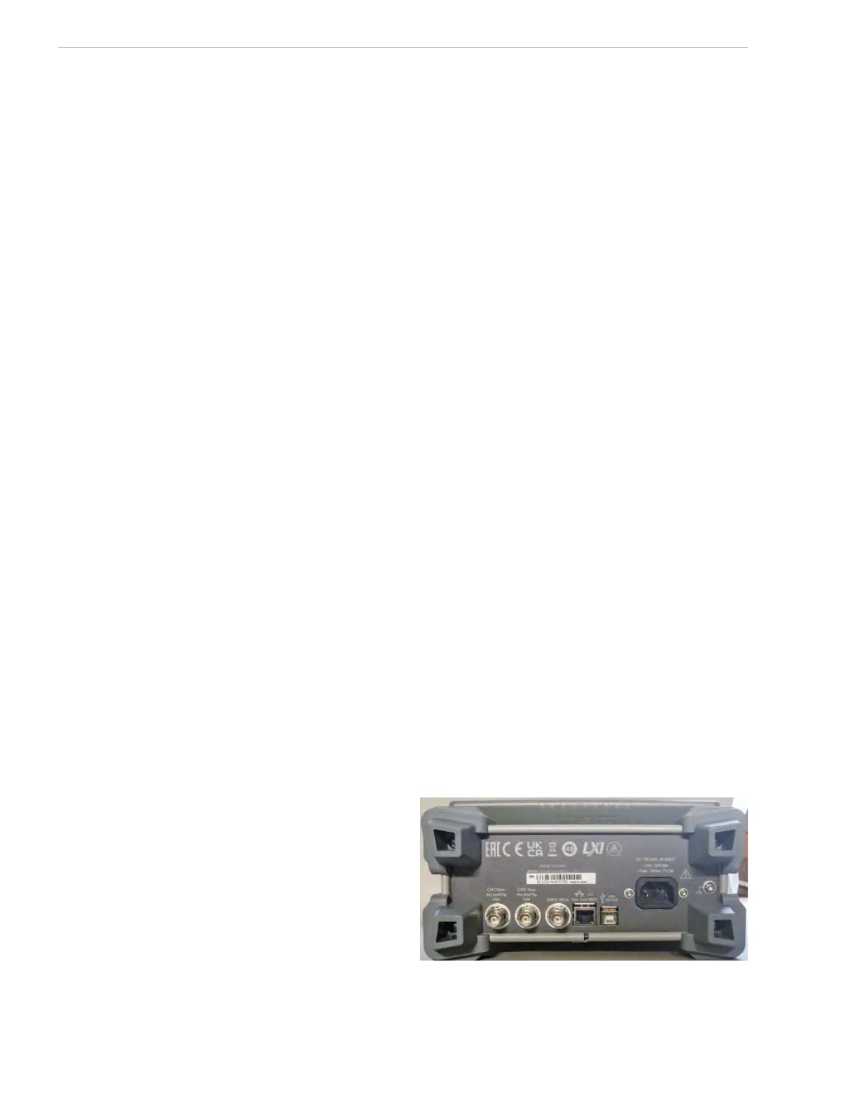
Figure 8 — The RIGOL DG1062Z rear panel.
 Loading...


