46 March 2023 QST www.arrl.org
JUNTEK JDS2900
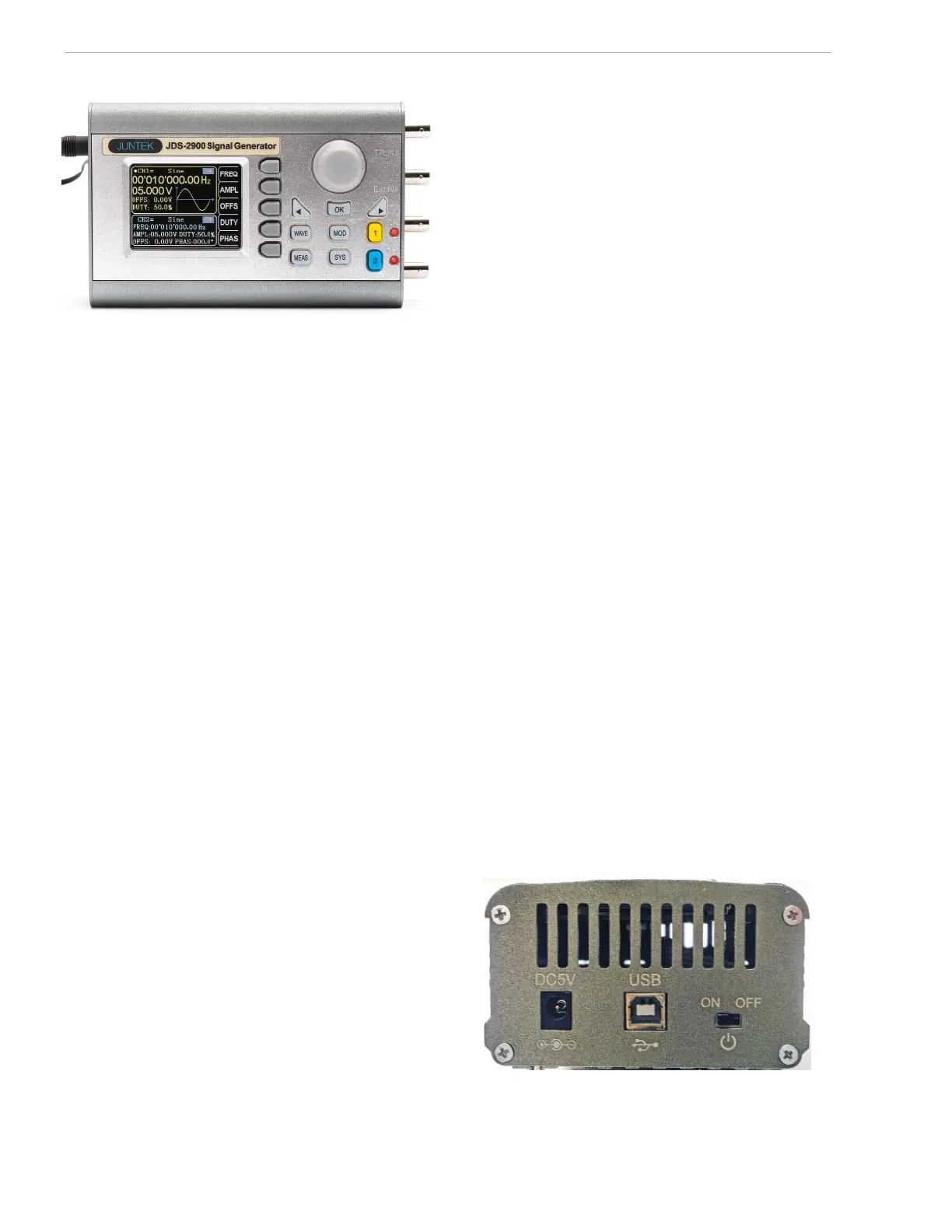
Figure 5 – The JUNTEK JDS2900 left side view, with the ON/OFF
switch, the 5 V dc power connection, and the USB connector.
show a square wave, but adjusting the amplitude of
the square wave will be re ected in the number on the
screen, not the height of the picture. A white illuminated
dot on the screen tells you which item is active and will
respond to control changes.
The round knob changes the digit of whatever is being
changed by your selection. Suppose the amplitude is set
to 3.500 V and the
5 digit is shown with a red marker.
Rotating the round knob clockwise will change the
5 value to 6, 7, 8, 9 in sequence. To jump quickly from
one digit place to the next, you can use the arrow keys.
The selected output is shown on the right side. To make
changes on channel 1, press the
1 button. To make
changes on channel 2, press the
2 button. The associ-
ated LEDs remind you what selection you made when
illuminated.
It is easy to forget where you are when making complex
selections. To reset, slide the power switch off — this
may be drastic, but it might be the only way to get back
to where you want to select a signal.
There are 20 selectable waveforms from the front panel.
This review covers only the front panel capabilities;
there are 14 arbitrary programmable waveforms that
can be set up and stored for immediate recall through a
computer interface.
Available Waveforms
Per the list in the Quick Guide, the following xed wave-
forms are selectable: sine, square pulse (with adjustable
width and period), triangular wave, partial sine wave,
TTL/CMOS wave, adjustable DC level, half sine wave,
positive- and negative-going staircase wave, noise
wave, up exponential rise, down exponential, and sev-
eral others. There are more than 14 programmable slots
for your choice of non-standard waveforms that can be
stored.
A full explanation of each of the buttons for each mode
or waveform would take several pages of instruction,
This almost pocket-sized waveform generator front
panel is approximately 4 × 1.5 × 4 inches. It has two
modes of operation: functions that can be called up and
their settings adjusted for the front panel, and functions
that can be set up and adjusted only by software
installed on a personal computer or laptop.
The package comes with the basic unit, a wall wart
power supply, a mini CD, and a set of cables. The
quick-start booklet included in the package is minimal;
there is a full set of instructions and descriptions on the
CD. The le is named
DDS_SETUP. Drag it to your desk-
top and uncompress with a tool like 7Zip or another
uncompressing tool. Open the following folders/ les in
this order:
SIGNAL GENERATOR SOFTWARE, ENGLISH,
and
QUICK GUIDE. The Quick Guide PDF has both the
full instructions and a list of the manufacturer’s speci -
cations.
Inputs and Outputs
The left side panel has a socket labeled DC5V that
mates with the cord from the power supply. Next to it is
a
USB (type B) socket for connection to a PC. Finally, to
its right is the unit’s
ON/OFF switch (see Figure 5).
On the right side are four BNC connectors labeled
TTLIN, EXTIN, CH1, and CH2. The last two have LEDs to
indicate which channel is active (it may indicate that
both are active). Unfortunately, the lettering for these
four connectors may be difficult to see under poor light-
ing conditions.
The mini CD has all the buttons on the front panel
shown in a pictorial with callouts of their names or func-
tions. Not labeled are the two arrow keys just below the
single rotary knob (to be described later).
Front Panel — Watch the Numbers, Not the Picture
For the most part, the waveforms on the front panel
vary only with major changes in selection. For example,
pressing the
WAVE button to select a square wave will
 Loading...


