accessible I/O headers for the user including SPI, I2C, UART, digital I/O, analog input, encoder input, and PWM
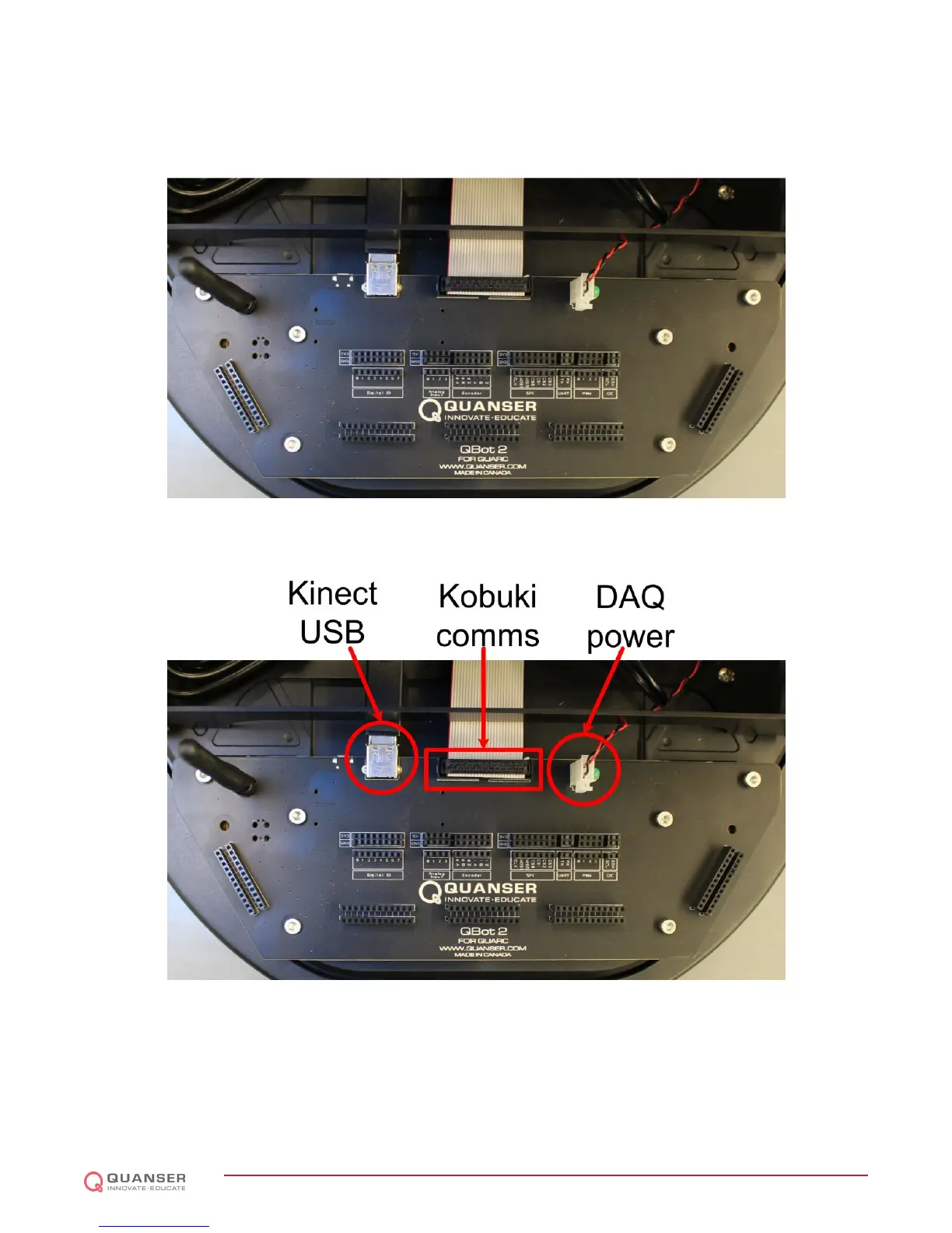
output. More details on accessing the QBot 2 I/O is found in 2.6. The QBot 2 DAQ connects to the Kinect sensor
via a USB port (see Figure 2.4). The QBot 2 DAQ connects to the Kobuki via a ribbon cable (see Figure 2.4). The
QBot 2 DAQ is powered via a cable connected to the Kobuki 12 V, 5 A power source (see Figure 2.4).
Figure 2.3: The QBot 2 DAQ
Figure 2.4: The QBot 2 DAQ connectors
The QBot 2 DAQ also provides five headers for users to use when integrating additional I/O components. Each
header is a double row where each pin in the first row is electrically connected to the pin in the second row directly
opposite. This allows users to connect a sensor to one row and map the connection from the DAQ I/O to the pins in
the mating row similar to a breadboard. Figure 2.5 shows the location of the headers.
QBOT 2 - User Manual
DRAFT - April 14, 2015
 Loading...