EasyManua.ls Logo

Quantec Surveyor 2 - User Manual

Quantec Surveyor 2
4 pages
Print Icon
To Next Page IconTo Next Page
Loading...
Approved Document Number DNU6500005 Rev 4
1
/4
Quantec Surveyor 2
Te c h n i c a l I n s t a l l a t i o n D o c u m e n t
Providing a site with the Surveyor 2 service has been made as simple as possible and should take no longer than
30 minutes to implement. You will need to install one IOT Connect Card (Part No: QTS2/5) into every Quantec
Controller that you would like to connect to the service (mounting posts and connectors are provided).
Important Note: The NVM link on the Quantec Controller’s mainboard must be permanently fitted BEFORE
installing the IOT Connect Card as the link will be hidden when the IOT Connect Card is installed.
The IOT Connect Card connects to the Surveyor 2 service via the internet using Ethernet cable (not supplied).
Ensure that network access rules whitelist quantecservice.c-tec.co.uk on port 80.
IOT Connect Card Connection Points and Status LEDS (shown above)
1. Ethernet (RJ-45) CAT-5 connection to the building internet. Ethernet cable not supplied. The Green light
on this connector turns on when the Ethernet connection is live. BEFORE the IOT Connect Card will
connect to the internet, the card must be configured (see page 2).
2. RS232 4-way serial port. Using the supplied cable connect to the 4 pin serial header on the Quantec
mainboard.
3. 24V 2-way Power connector. Using the supplied cable connect to 0V & 24V supply on the Quantec
mainboard.
4. Status LEDs:
POWER (Green):
Will turn on when the IOT Connect Card is receiving power
RUN (Green):
Will turn on after firmware has initialized and is running
LINK (Yellow):
Will blink on every data transfer
ERROR (Red):
1. Will turn on when a network error has occurred, e.g. cannot reach destination. When
this occurs the current operation is latched and re-tried every 30 secs. A signal is also sent
to the Quantec Controller to hold off further reporting until this operation succeeds.
2. The IoT Setup app has connected from your device to the IoT Connect Card.
5. IOT Connect Card shutdown button (Red).
1
2
3
4
5
Question and Answer IconNeed help?

Do you have a question about the Quantec Surveyor 2 and is the answer not in the manual?

Overview

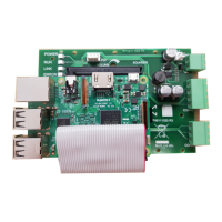
The Quantec Surveyor 2 is a device designed to connect Quantec Controllers to the Surveyor 2 service via the internet, enabling remote monitoring and management. This technical installation document outlines the process for setting up and configuring the IOT Connect Card (Part No: QTS2/5), which is the core component for this connectivity.

Function Description:

The IOT Connect Card acts as a bridge between a Quantec Controller and the internet-based Surveyor 2 service. It allows the Quantec Controller to transmit data and receive commands, facilitating remote access and management of the connected system. The device is designed for straightforward installation, aiming for a setup time of no more than 30 minutes per controller. It utilizes an Ethernet connection for internet access, requiring a standard CAT-5 Ethernet cable (not supplied) and whitelisting of quantecservice.c-tec.co.uk on port 80 in the network access rules.

Important Technical Specifications:

  • Part Number: QTS2/5 (IOT Connect Card).
  • Connectivity:
    • Ethernet (RJ-45): CAT-5 connection for internet access. Features a Green LED to indicate a live Ethernet connection.
    • RS232: 4-way serial port for connection to the Quantec mainboard using a supplied cable.
    • Power: 24V 2-way power connector for connection to the OV & 24V supply on the Quantec mainboard using a supplied cable.
  • Status LEDs:
    • POWER (Green): Indicates the IOT Connect Card is receiving power.
    • RUN (Green): Illuminates after firmware initialization and indicates the device is running.
    • LINK (Yellow): Blinks during every data transfer.
    • ERROR (Red):
      • Turns on for network errors (e.g., cannot reach destination). When active, the current operation is latched and retried every 30 seconds. A signal is also sent to the Quantec Controller to pause further reporting until the operation succeeds.
      • Also turns on when the IoT Setup app has connected from a device to the IOT Connect Card during configuration.
  • Shutdown Button: A Red button is provided for powering down the IOT Connect Card.
  • Firmware Requirement: Quantec Controller firmware version 10A9 or above is required.

Usage Features:

  • Installation: The IOT Connect Card is installed into a Quantec Controller using provided mounting posts and connectors. A critical pre-installation step is ensuring the NVM link on the Quantec Controller's mainboard is permanently fitted, as it will be concealed by the IOT Connect Card.
  • Configuration:
    • Configuration is performed using the 'C-TEC IoT Setup' app on a mobile device (phone/tablet).
    • The app allows selection of correct options for "Panel Type," "Panel Comms," "Network," and "Bus Option."
    • The mobile device needs to be held within 30 cm of the IOT Connect Card during configuration. If multiple Surveyor 2 devices are nearby, power should be removed from other devices to ensure connection to the correct unit.
    • Pressing the "Configure" button transfers settings to the IOT Connect Card. The Yellow Error light will illuminate during this process, indicating a connection to the mobile device.
    • A green tick in the app confirms successful configuration.
    • After any configuration update, the IOT Connect Card will reboot, which may take up to 5 minutes.
  • Pairing with Surveyor 2 Service:
    • Once configured, the Quantec panel's display will show a unique pairing code.
    • This code is used to register the panel with the Surveyor 2 provider account at quantec.c-tec.co.uk.
    • Within the provider portal, new sites can be added, and panel information (SiteName, Telephone, Address, Site Package Type, Site Administrator details) can be entered.
    • Panels are added to a site by entering their pairing code in the "Panel Status" section of the provider portal. The system confirms successful pairing.
    • The panel's name in the portal can then be changed from the pairing code to a more meaningful identifier.
  • IoT Setup App for Status Information: In case of issues with RUN, LINK, or ERROR indicators, the IoT Setup app can be used to retrieve status information about the connection.

Maintenance Features:

  • Firmware Check: Before installation, it's crucial to confirm the Quantec Controller's firmware version is 10A9 or above by pressing the 'Escape' button on the controller.
  • NVM Link: The NVM link on the Quantec Controller's mainboard must be permanently fitted and should never be removed, as it is essential for the IOT Connect Card's operation and will be inaccessible after installation.
  • Surveyor Mode: The Quantec Controller's menu keys must be used to enter access level 3 and 'Enable' Surveyor Mode.
  • Troubleshooting:
    • If the Red ERROR LED turns on, users should verify that all installation and configuration steps have been correctly followed and check the building's network connection.
    • The Green light on the Ethernet connector indicates a live connection.
    • The Green POWER and RUN LEDs on the IOT Connect Card should be on after powering up.
  • Reconfiguration: If network or configuration settings change, the IOT Connect Card can be reconfigured using the IoT Setup app. This involves powering down the card, disconnecting and reconnecting power, and then re-applying power after connecting to the building's Ethernet.

Quantec Surveyor 2 Specifications

General IconGeneral
BrandQuantec
ModelSurveyor 2
CategoryComputer Hardware
LanguageEnglish