Positive Wire
Negative Wire
Page 11
AWD - Setup
incorrectly it could cause damage to the movers or caravan tyres if all rollers do not move in the correct directions.
WARNING: EACH CONTROL BOX MUST BE POWERED INDEPENDENTLY FROM THE BATTERY THROUGH THE
SAME ISOLATION SWITCH (TWO POSITIVE AND TWO NEGATIVE WIRES). CONNECTING THE BOXES DIRECTLY
(PIGGY BACKING) COULD OVERLOAD/DAMAGE THE SYSTEM. BEFORE TURNING ON THE ISOLATION KEY ENSURE THAT
BOTH NEGATIVE CABLES ARE CONNECTED TO THEIR RESPECTIVE CONTROL BOX, FAILURE TO DO THIS WILL ALSO
CAUSE DAMAGE TO ONE/BOTH BOXES.
Fig.5.
2. Ensure the link cable is connected into port E on both control boxes.
3. Turn on the isolation switch to supply power to both control boxes.
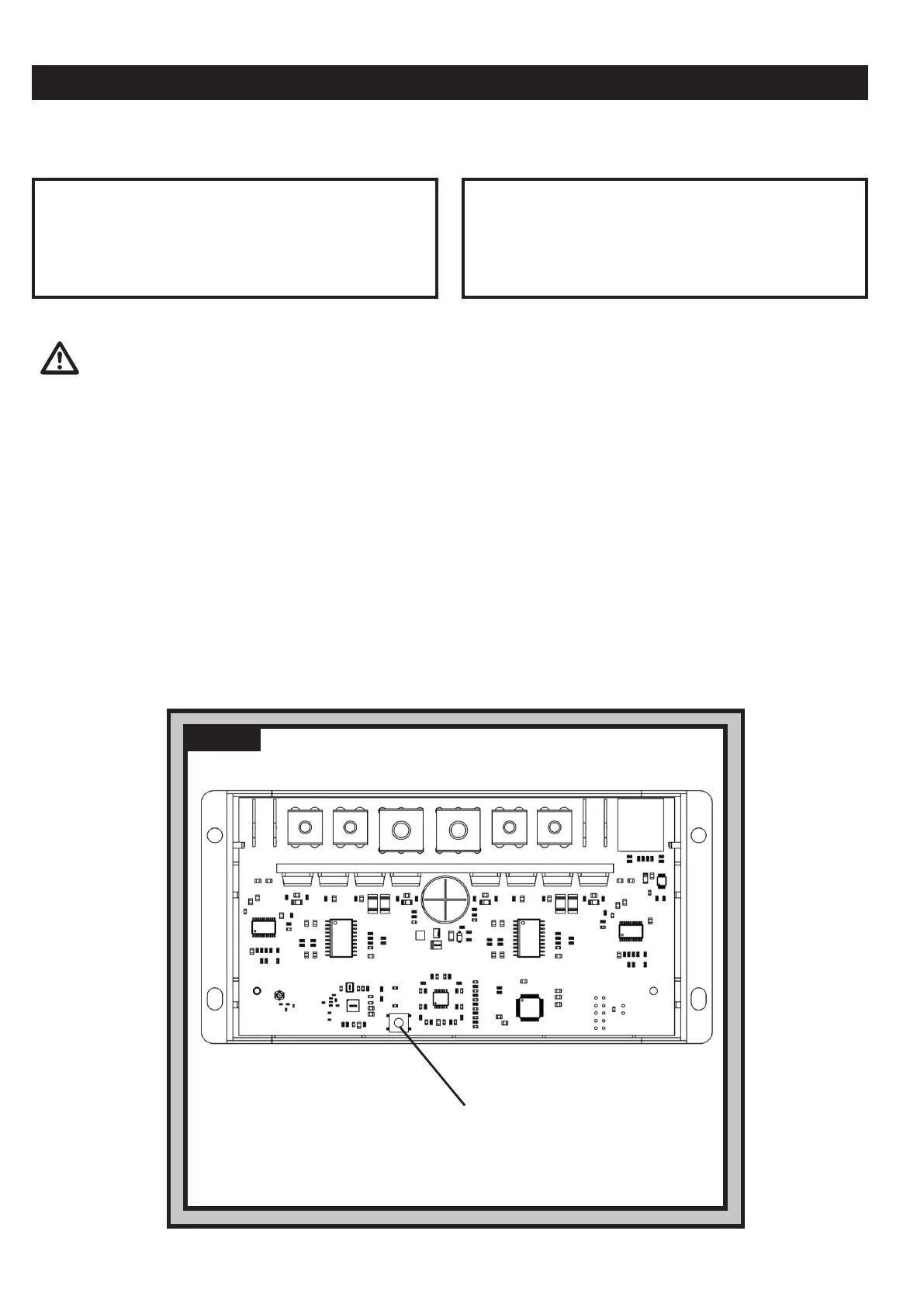
4. Press button Fig.6A located on the slave control box that is powering the rear axle.
5. Power on handset by double-pressing button Fig.1C on the handset.
the handset and control box will need to be reset.
10. Power on system and handset and ensure that all wheels are rotating in the correct direction, installation is now complete.
Motor A Positive (+) cable to terminal M2+
Motor A Negative (-) cable to terminal M2-
Motor B Positive (+) cable to terminal M3+
Motor B Negative (-) cable to terminal M3-
AWD - REAR AXLE FITTING
Motor A Positive (+) cable to terminal M3+
Motor A Negative (-) cable to terminal M3-
Motor B Positive (+) cable to terminal M2+
Motor B Negative (-) cable to terminal M2-
AWD - FRONT AXLE FITTING
Table . BTable . A
Fig.6A
Fig.6A
Push this button on the rear-axle slave control box.
Note: The Blue LED will turn o once activated.


 To Next Page
 Loading...