10. Remove the spacer and encoder disc.
11. Using a marker or pencil, mark a line on the upper end bell extending it onto the motor frame. Do the
same for the lower end bell and frame. When reassembling the motor, align the marks on the frame
with the marks on the end bells to ensure that the motor is reassembled in the same orientation that it
was before disassembly.
12. Remove the four long bolts that secure the end bells to the motor frame. Tap on the upper end bell with
a mallet to free the end bell from the upper rotor bearing.
13. Pull the rotor and lower end bell away from the motor frame. The rotor will remain attached to the lower
end bell until the next two steps are performed. The upper end bell, while loose, cannot be completely
removed because of the wiring connections. Take care to prevent damaging the motor’s wiring.
14. There is a wave spring that will either remain in the recess on the inside of the upper end bell (if it is,
leave it there) or could have stuck to the upper bearing of the rotor assembly when the rotor was
removed. If the wave spring is on the rotor bearing, remove it and save for reuse.
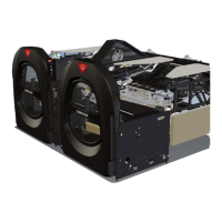
15. Loosen the screw on the lower end bell (see
the illustration at the right) and rotate the dog
away from the rotor assembly’s lower bearing.
Remove the rotor assembly.
16. Remove the key taped to the new rotor
assembly, and insert the shaft of the new rotor
through the opening in the lower end bell so
that the bearing seats within the recess in the
end bell. (You may need to tap the end bell
with the mallet.)
17. Tighten the screw in the lower end bell (see above). Ensure that the dog rotates over the bearing and
stops against the roll pin. Tighten the screw securely.
18. If the wave spring was removed from the recess in the upper end bell, place the wave spring into the
recess in the upper end bell and insert the rotor assembly into the frame and through the hole in the
upper end bell. Ensure that the upper bearing is seated within the recess in the end bell. Use the
mallet to seat the bearing, if necessary.
 Loading...