15 - reset ALL counters
Parameter no. 100 – Enable / Disable endpoints IR
external relay and External relay
Enabling IR external relay and External relay or both of
them, means that endpoint (IR external relay) and
endpoint (External relay) or both will be present on UI.
Disabling them will result in hiding endpoints according to
Parameter set value. Note that hiding endpoint has no
impact on its functionality. Available configuration
parameters (data type is 1 Byte DEC):
default value 0
0 - Endpoints IR external relay and External relay
disabled
1 - Endpoints IR external relay disabled, External
relay enabled
2 - Endpoints IR external relay enabled, External
relay disabled
3 - Endpoints IR external relay and External relay
enabled
NOTE1: After parameter change, first exclude module
(without setting parameters to default value) and then re
include the module.
NOTE 2: If you don't have IR BiComm relay module
mounted and you enable IR communication (parameter
100 is 2 or 3) there will be no valid IR relay state reported.
It will be reported IR COMMUNICATION ERROR and
LED2 will BLINK.
Parameter no. 110 - Maximum Power auto off
Set value means Maximum Power Consumption (0 -
15000) in watts (W), when relays are turned off according
to parameters no. 111 and 112. Available configuration
parameters (data type is 2 Bytes DEC):
default value 0
0 - no function
1 - 15000 = 1 W - 15000 W Maximum Power
Consumption.
Parameter no. 111 - Delay overpower off
Set value means number of second to power off relay
(defined by parameters no. 110 and 112) before restart
(30 - 32535) in seconds (s). Available configuration
parameters (data type is 2 Bytes DEC):
default value 30
30 – 32535 = 30 s – 32535 s delay.
Parameter no. 112 - Relay to power off
Set value selects relay to be powered off when threshold
is reached (defined by parameters no. 110 and 111).
Available config. parameters (data type is 1 Byte DEC):
default value 0
0 - switch between the 2 relays (power off relay 1
first, after power on, if power consumption is still
over, power off relay 2, ..)
1 - always power off relay 1 (IR external relay)
2 - always power off relay 2 (External relay)
3 - always power off both relays (relay 1 and relay 2)
Parameter no. 130 – Serial Number
Read only. Unsigned Value (32bit)
Parameter no. 131 – Meter Software reference Read
only. Unsigned Value (16bit). 2 decimal places.
Parameter no. 132– Meter Hardware reference Read
only. Unsigned Value (16bit), 2 decimal places.
Parameter no. 140– Voltage U1
Read only. Unit: V. Binary Unsigned Value (24bit), 1
decimal place.
Parameter no. 141– Current I1
Read only. Unit: A. Binary Unsigned Value (24bit), 3
decimal places.
Parameter no. 142– Active Power Total (Pt)
Read only. Unit: W. Binary Signed Value (24bit), 1
decimal place.
Parameter no. 143– Reactive Power Total (Qt)
Read only. Unit: kVAR. Binary Signed value (24bit), 1
decimal place.
Parameter no. 144– Power Factor Total (PFt)
Read only. Unsigned Value (16bit), 4 decimal places.
Parameter no. 145– Energy Counter 1 – Active power
accumulated (import)
Read only. Unit: Kwh. Signed Long Value (32bit), 1
decimal place.
Parameter no. 146– Energy Counter 2 – Reactive
power accumulated
Read only. Unit: kVARh. Signed Long Value (32bit), 1
decimal place.
Parameter no. 147– Energy Counter 3 – Apparent
power accumulated
Read only. Unit: KVAh. Signed Long Value (32bit), 1
decimal place.
Parameter no. 148– Energy Counter 4 – Active power
accumulated (export)
Read only. Unit: Kwh. Signed Long Value (32bit), 1
decimal place.
Technical Specifications
Main terminals (LI, NI, Lo, No)
Contacts capacity: 1.5 ... 16 (25) mm
2
Connection screws: M5
Max torque: 3.5 Nm (PZ2)
Optional terminals (1,2,4,5)
Contact capacity: 0.05 ... 1 (2.5) mm
2
Screws: M3
Max torque: 0.6 Nm
Measuring input:
Type (connection): single phase (1b)
Reference current (Iref): 5 A
Maximum current (Imax): 65 A
Minimum current (Imin): 0.25 A
Starting current: 20 mA
Voltage (Un): 230 V (±20 %)
Power consumption at Un: < 2W
Nominal frequency (fn): 50 and 60 Hz
Accuracy:
Active energy and power:
Standard EN 62053-21: class 1
Standard EN 50470-3: class B
Reactive energy:
Standard EN 62053-23: class 2
Optical communication:
Type: IR - used to control
BICOM432-40-IR
Input (1):
Rated voltage: 230 V (± 20%)
Input resistance: 450 kOhm
Safety:
Indoor Meter: yes
Degree of pollution: 2
Protection class: II
AC voltage test: 4 kV
Installation Category: 300 Vrms cat. III
Standard: EN 50470
Ambient conditions and EMC:
According standards for indoor active energy Meters.
Temperature and climatic condition according to
EN 62052-11
Ambient conditions and Safety:
According standards for indoor active energy Meters.
Temperature and climatic condition according to
EN 62052-11
Dust/water protection: IP20
Operating temperature: -10 ... 55°C
Storage temperature: -40 ... 70°C
Enclosure material: self extinguish
complying UL94 V
Indoor Meter: yes
Degree of pollution: 2
AC voltage test: 4 kV
Standard: EN 50470
Distance: up to 30 m indoors
(depending on building
materials)
Weight (with packaging): 150g (170g)
Frequency range: 868.4 MHz, Z-Wave
Installation Din rail 35mm
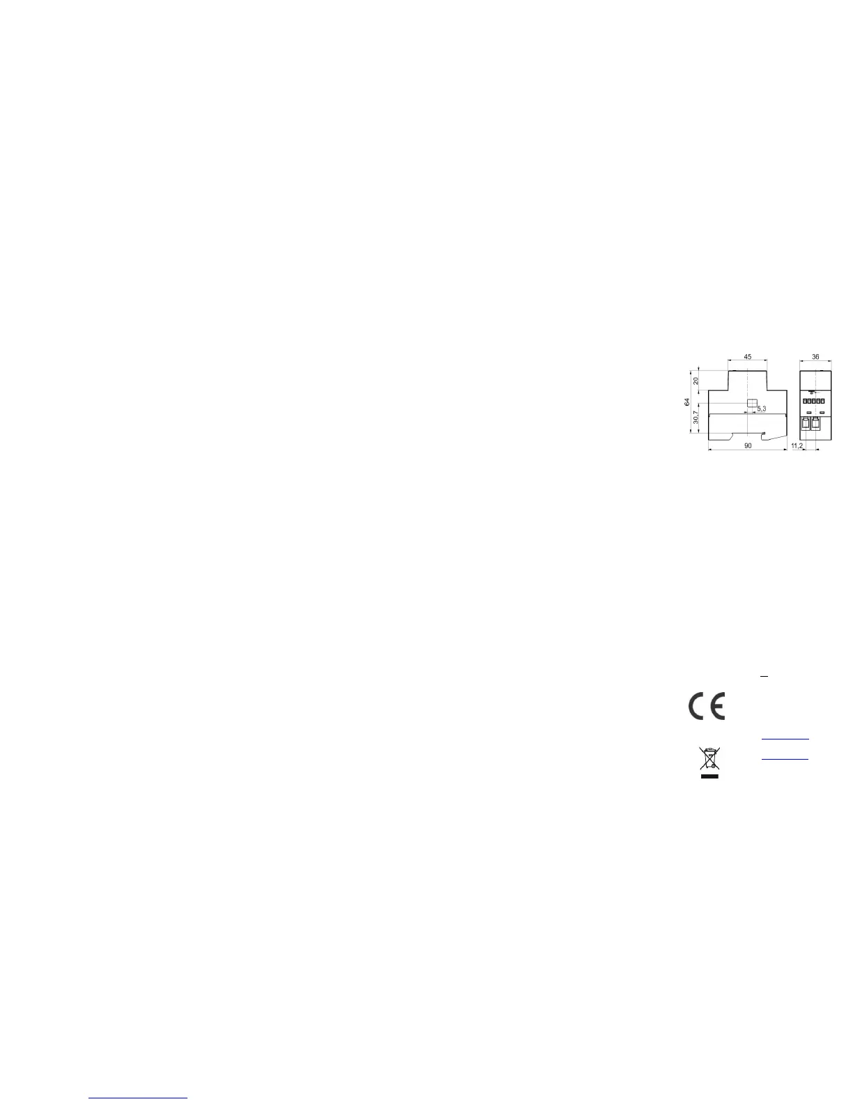
Dimensions (W x H x D): 36 x 90 x 64mm
Package dimensions
(W x H x D): 40 x 95 x 80mm
Colour RAL 7035
EC Directives conformity:
EC Directive on Meas. Instruments 2004/22/EC
EC Directive on EMC 2004/108/EC
EC Directive on Low Voltage 2006/95/EC
EC Directive WEEE 2002/96/EC
Z-Wave Device Class:
ZWAVEPLUS_INFO_REPORT_ROLE_TYPE_SLAVE_ALWAYS_0N
GENERIC_TYPE_METER
SPECIFIC_TYPE_WHOLE_HOME_METER_SIMPLE
Z-Wave Supported Command Classes:
COMMAND_CLASS_ZWAVEPLUS_INFO_V2
COMMAND_CLASS_BASIC
COMMAND_CLASS_SWITCH_ALL
COMMAND_CLASS_SWITCH_BINARY_V2*
COMMAND_CLASS_METER_V4
COMMAND_CLASS_MULTI_CHANNEL_V4
COMMAND_CLASS_MULTI_CHANNEL_ASSOCIATION_V3
COMMAND_CLASS_CONFIGURATION
COMMAND_CLASS_VERSION_V2
COMMAND_CLASS_MANUFACTURER_SPECIFIC_V2
COMMAND_CLASS_DEVICE_RESET_LOCALLY
COMMAND_CLASS_POWERLEVEL
COMMAND_CLASS_ASSOCIATION_V2
COMMAND_CLASS_ASSOCIATION_GRP_INFO_V2
COMMAND_CLASS_DEVICE_RESET_LOCALLY
COMMAND_CLASS_CRC_16_ENCAP
COMMAND_CLASS_FIRMWARE_UPDATE_MD_V2
COMMAND_CLASS_MARK
COMMAND_CLASS_BASIC
COMMAND_CLASS_SWITCH_BINARY_V2*
*valid if endpoints enabled
Endpoint 1 (IR external relay):
Device Class:
GENERIC_TYPE_SWITCH_BINARY
SPECIFIC_TYPE_POWER_SWITCH_BINARY
Command Classes:
COMMAND_CLASS_ZWAVEPLUS_INFO_V2
COMMAND_CLASS_BASIC
COMMAND_CLASS_SWITCH_BINARY_V2
COMMAND_CLASS_ASSOCIATION_V2
COMMAND_CLASS_ASSOCIATION_GRP_INFO_V2
COMMAND_CLASS_MULTI_CHANNEL_ASSOCIATION_V3
COMMAND_CLASS_MARK
COMMAND_CLASS_BASIC
Endpoint 2 (External relay):
Device Class:
GENERIC_TYPE_SWITCH_BINARY
SPECIFIC_TYPE_POWER_SWITCH_BINARY
Command Classes:
COMMAND_CLASS_ZWAVEPLUS_INFO_V2
COMMAND_CLASS_BASIC
COMMAND_CLASS_SWITCH_BINARY_V2
COMMAND_CLASS_ASSOCIATION_V2
COMMAND_CLASS_ASSOCIATION_GRP_INFO_V2
COMMAND_CLASS_MULTI_CHANNEL_ASSOCIATION_V3
COMMAND_CLASS_MARK
COMMAND_CLASS_BASIC
NOTE:
- Endpoints are shown/hidden by Parameter No.
100
- BASIC SET/GET on root device is mapped to
basic set/get of both endpoints.
This product can be included and operated in any Z-Wave
network with other Z-Wave certified devices from any
other manufacturers. All constantly powered nodes in the
same network will act as repeaters regardless of the
vendor in order to increase reliability of the network.
Dimensional drawings:
Important disclaimer
Z-Wave wireless communication is inherently not always
100% reliable, and as such, this product should not be
used in situations in which life and/or valuables are solely
dependent on its function.
Warning!
Do not dispose of electrical appliances as unsorted
municipal waste, use separate collection facilities. Contact
your local government for information regarding the
collection systems available. If electrical appliances are
disposed of in landfills or dumps, hazardous substances
can leak into the groundwater and get into the food chain,
damaging your health and well-being. When replacing old
appliances with new once, the retailer is legally obligated
to take back your old appliance for disposal at least for
free of charge.
This user manual is subject to change and improvement
without notice.
NOTE: User manual is valid for module with SW version
S4,S5&S6 (SW version is part of P/N)!
Example: P/N: ZMNHTDx HxS6Px
Qubino
Goap d.o.o. Nova Gorica
Ulica Klementa Juga 007
5250 Solkan Slovenia
E-mail: info@qubino.com
Tel: +386 5 335 95 00
Web: www.qubino.com
Date: 15.11.2016
Document: Qubino_Smart Meter
PLUS user manual_V1.7_eng
 Loading...