FFLED INSTALLATION INSTRUCTIONS
Thank you for buying RAB lighting xtures. Our goal is to design the best quality products to get the job done right. We’d like to hear your comments.
Call the Marketing Department at 888-RAB-1000 or email: marketing@rabweb.com
Note: These instructions do not cover all details or variations
in equipment nor do they provide for every possible situation
during installation, operation or maintenance.
Patent - US: Pat D643,147
ACCESSORIES AND REPLACEMENT
PARTS
Chrome Wire Guard: GDFFLED39W
Poly Shield: GDFFLED39P
Lens & Door Replacement: LFFLED39 (bronze)
LFFLED39W (white)
Easy Installation & Product Help
Tech Help Line
Call our experts 888 RAB-1000
©2015 RAB LIGHTING Inc.
Northvale, New Jersey 07647 USA
rabweb.com
Visit our website for product info
email
Answered promptly sales@rabweb.com
FFLED263952 IN 0315
GUARD OR SHIELD INSTALLATION
Wire Guard and Poly Shield mount with (4) #8-32 Stainless
Steel Screws. Screws are provided with accessory. Guard
and Shield may be used together. See gure 1 for Guard. See
gure 2 for Shield
1. Line up guard with pre-existing, pre-drilled holes in
frame as shown, tighten screws.
Stainless Steel
Screws (4)
Figure 1
Figure 2
Stainless Steel
Screws (4)
ONOFF WIRING
Universal voltage driver permits operation at 120V to 277VAC,
50 or 60Hz, except xtures factory ordered with a 120V
photocell (/PC), 120V swivel photocell (/PCS), 277V photocell
(/PC2) and 277V swivel photocell (/PCS2). Units ordered with
(/480V) sux are 480V. For Non-Dimming, follow the wiring
directions as in g. 1.
1. Connect the black xture lead to the (+) LINE supply lead.
2. Connect the white xture lead to the (-) COMMON supply
lead.
3. Connect the bare copper Ground wire from xture to
supply ground.
LIGHT
FIXTURE
(+)LINE BLACK
(-)COMMON WHITE
GROUND GROUND
Fig. 1
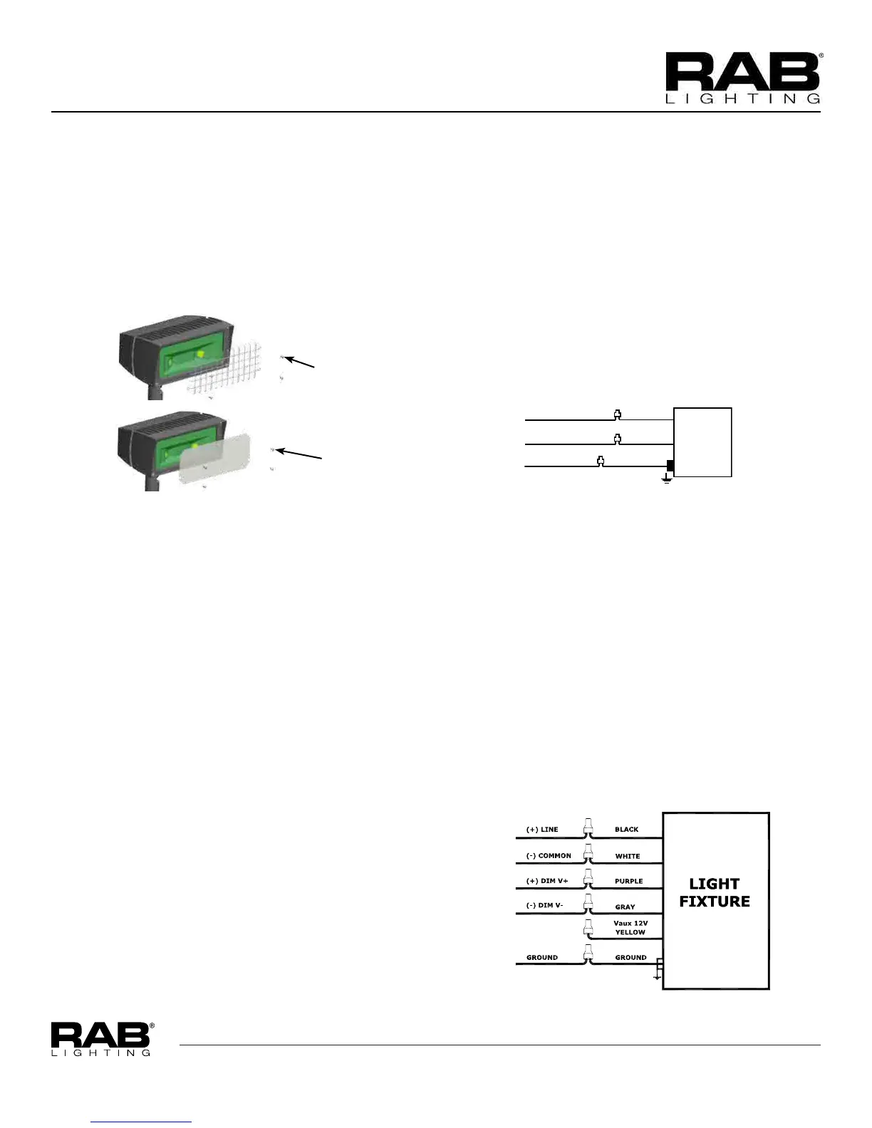
010V DIMMABLE WIRING
Universal voltage driver permits operation at 120V thru 277V,
50 or 60 Hz. For 0-10V Dimming, follow the wiring directions
as in g. 2.
1. Connect the black xture lead to the (+) LINE supply lead.
2. Connect the white xture lead to the (-) COMMON supply
lead.
3. Connect the GROUND wire from xture to supply ground.
Do NOT connect the GROUND of the dimming xture to
the output.
4. Connect the purple xture lead to the (V+) DIM lead.
5. Connect the gray xture lead to the (V-) DIM lead.
6. Cap the yellow xture lead, if present. Do NOT connect.

 Loading...