P.C.B. SM 20015 – boiler settings
16
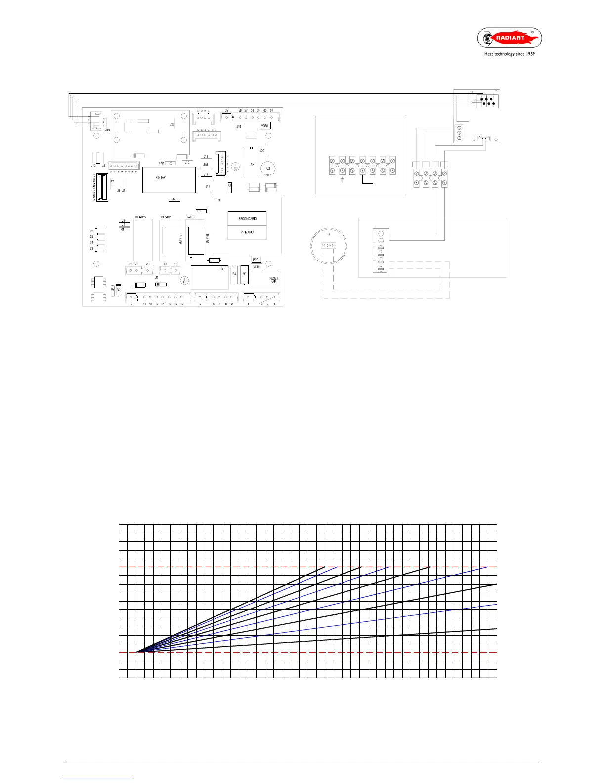
WIRING DIAGRAM FOR REMOTE CONTROL INSTALLATION (no zone valves)
Fit the interface (fig. 2) on the circuit board (fig. 1) into the holes A and B provided (see fig. 1).
Connect plug M1 on the interface circuit board (fig. 2) to plug M11 on the modulation circuit board (fig. 1).
Connect the grey and orange wires in plug M2 of the interface circuit board (fig. 2) and in the terminal block (fig.
4).
Connect the wires of plug M3 on the interface circuit board (fig. 2) in the terminal (fig. 4).
Remove the link TA-TA (fig. 3) and set the boiler to SUMMER mode.
Connect the remote control to the terminal block (fig. 4) using a cable with a minimum section of 2 x 0.5 mm2
section and max. length of 50 m being careful to observe the +/- polarity.
THE EXTERNAL SENSOR IS OPTIONAL. The connection can be made to either the remote control (fig. 5) or to
the terminal block (fig. 3 - dotted line) on the terminals marked SE-SE.
WARNING! The remote control connection cable must pass through a channel which is separate from any system
supplied with power. If this is not possible, fit a screened cable.
M6
M4
M3
M5
M2 M1
M4
M13
M7
M11
M8
M12
M10
M9
EXTERNAL SENSOR
2M1
1
TELS EXT
IN
-
+
REMOTO
N
L
Se
TA
TA
Se
LINE
Fig. 3
EARTH
NEUTRAL
EXTERNAL
SENSOR
ROOM
THERMOSTAT
5+VZ
Fig. 4
4-
RL1
orange
grey
M3
M2
7 8
Fig. 2
M1
Interfaccia
13
EXTERNAL SENSOR
FLOW TEMPERATURE CORRECTION LAW HOW IN THE RELATION TO THE EXTERNAL
TEMPERATURE AND POSITION OF THE USER HEATING TEMP. ADJUSTMENT.
TM - MAX / MIN = Range of flow temperature selected
70
35
MIN
25
27 26
30
30
35
45
40
50
60
55
65
192425 23 2122 20 1618 17 15 14
Tm
MAX
40 80
75
Te = External temperature
Tm =
flow temperature
-121012 11 89
75
6
4
231 -6-3-10-2
-4 -5
-9
-7
-8 -10 -11
8
9
7
6
5
0
Te (°C)
-15-13 -14
1
2
3
4
Fig. 1
Fig. 5
P.B.C.
INTERFACE
REMOTE
AB
 Loading...