Do you have a question about the Radionics D9412G and is the answer not in the manual?
Explains the structure and sections of the manual for user guidance.
Lists all relevant documents with part numbers for comprehensive information.
Details type styles, notes, cautions, and warnings used throughout the guide.
Covers regulatory compliance with Part 15 and Part 68 of FCC rules.
Highlights key distinctions and feature variations between the D9412G and D7412G panels.
Provides detailed technical specifications for voltage, power, and connections.
Introduces and explains significant new functionalities like Ground Fault Detect and NetCom.
Covers core system capabilities such as points, areas, communicator, and command centers.
Outlines prerequisites and recommended documents before starting installation.
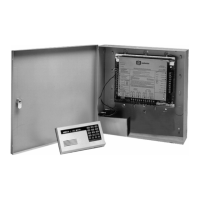
Details the available enclosure types for mounting the control/communicator.
Guides the initial physical steps of mounting the enclosure and running wires.
Provides instructions for securing the main panel assembly within the enclosure.
Explains the critical process of connecting the system to earth ground for safety.
Covers final steps including wiring devices, installing modules, and making connections.
Details how to load the system's custom program using the D5200 Programmer or RAM IV.
Outlines procedures for performing a complete functional test of the installed system.
Describes the primary AC power input and transformer installation.
Details the secondary DC power input, battery types, and installation.
Provides guidance on when and how to replace the system battery.
Explains the meaning and function of the charging and low battery indicator LEDs.
Details internal circuit protection mechanisms for power outputs.
Covers terminals for auxiliary power, ZONEX, and general power with current draw limits.
Explains the use of programmable relays for alarm and auxiliary functions.
Covers regulatory registration and notifying the telephone company.
Details the physical installation of the phone jack and cord.
Describes the red LED indicating phone line seizure status and green LED for CPU operation.
Details the system's capability to monitor the status of the phone line.
Addresses system status and troubleshooting for communication failures.
Explains the setup for ground start telephone systems.
Covers the installation and operation of the module for dual phone line support.
Describes how to wire and supervise on-board sensor loops.
Explains how point conditions are determined and measured.
Details how to configure the debounce count for point response.
Introduces POPIT modules for expanding system points via the ZONEX Bus.
Guides the installation and wiring of the POPEX module for point expansion.
Describes the integrated OctoPOPIT module combining POPEX and POPIT functions.
Provides instructions for testing all off-board points.
Details the OctoRelay module for adding multiple relay outputs to the system.
Explains the D811 module for adding a single arm status relay output.
Covers the function, installation, and address assignment of command centers.
Describes independent zone control units for point arming/disarming.
Explains the use of keyswitches for arming and disarming areas.
Covers the general installation process for SDI devices.
Details the module for connecting a parallel printer to the system.
Explains the module for access control points and door strikes.
Covers the use of SDI Address 80 for RS232 communication with automation software.
Details SDI Address 88 for programming modules and network interfaces.
Guides the connection and disconnection of the programming device and reports.
Explains how to connect accessories like the D928 Dual Phone Line Switcher.
Illustrates the physical layout and components of the D9412G faceplate.
Illustrates the physical layout and components of the D7412G faceplate.
Provides detailed wiring diagrams for the D9412G panel across three pages.
Provides detailed wiring diagrams for the D7412G panel across three pages.
Lists address assignments for ZONEX 1 points on both D9412G and D7412G panels.
Provides address assignments for ZONEX 2 points specific to the D9412G panel.
| Brand | Radionics |
|---|---|
| Model | D9412G |
| Category | Cell Phone |
| Language | English |