Chapter 3: DX Series
33
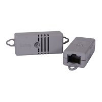
DX-VBR Terminals, dip switches and LED:
Numbers Components
One CC channel comprising a pair of terminals.
See
Connecting Detectors/Actuators to DX
(on page 34)
for how to connect a CC sensor.
Dip switch 1 configures the Normal state of the CC
channel.
Dip switch 2 does not control any CC channel and can be
ignored.
See
Adjusting Dip Switches
(on page 38).
CC status LED. For details, see
DX2-CC2 Contact Closure
Sensor LEDs
(on page 16).
High-speed flashing of CC1 LED indicates that the DX
firmware upgrade is in progress. See
Sensor Firmware
Update
(on page 79).
 Loading...