UV-USA_CAN SCC_WE, CM_P V06, 11/2016
17
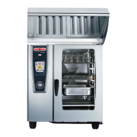
For UV connection 61-102E SI type with LED door ilumination
Reference picture 1 below highlighted in Blue with Through connection on A7 LED adapter
pcb in Red.
Pic 1
UV-USA SCC_WE, CM_P V05, 12/2015
37IA
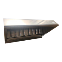
The original S3 door switch was conneced to X4 of A7 pcb, This will move to the T adapter pcb
for the UV onto x27.2 as shown in picture 2, an adapter cable will be added from X4 on A7 to
X27.1 on T adapter pcb. Finally the 8‘ long cable to the UV hood connection will be plugged
into x23.1 on T adapter pcb and then the two bare stripped wire ends inserted into terminal 4-
5 of UV..
Pic 2
The jumper cable from main pcb X27 to X3 on A7 Led adapter pcb is as from manufacturer.
 Loading...