RISERVATO AL PERSONALE AUTORIZZATO ALL'INSTALLAZIONE - ONLY FOR INSTALLATION-AUTHORIZED STAFF
IST DEM ZUR INSTALLATION AUTORISIERTEN PERSONAL VORBEHALTEN - SEULEMENT POUR LE PERSONNEL AUTORISE A L'INSTALLATION - RESERVADO AL PERSONAL ENCARGADO DE LA INSTALACION
16 0424-M001-1
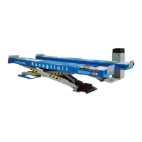
3.4 Installazione KP118-KP118P
Con riferimento alla Fig. 5 installare le traverse KP118-KP118P
all'interno della fossa agendo nel modo seguente:
- sollevare la traversa;
- spostarla all'interno della fossa;
- abbassare lentamente la traversa fino a una distanza di circa
5 cm dalla fossa;
- posizionare lo sfilo della traversa in funzione della distanza
dai bordi della fossa;
- calare la traversa posizionando gli appoggi sui bordi della
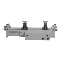
fossa, verificarne lo scorrimento ed avvitare le viti ad esago-
no incassato 1 (Fig.5) senza bloccarle completamente;
- eseguire il primo sollevamento a pieno carico (con auto sulla
3.4 Installation KP118-KP118P
Referring to Fig. 5, install wheel free jacks KP118-KP118P into
the pit as follows:
- raise the wheel free jack;
- move the wheel free jack into the pit;
- slowly lower the wheel free jack up to about 5 cm from the pit;
- position the wheel free jack support plate according to the
width across pit edges;
- position supports on pit edges and let jack come down. Check
for proper sliding and tighten Allen screws 1 (Fig. 5) without
locking them fully;
- First lift the jack with full load (with a car on the jack), then fully
lock Allen screws 1 (Fig. 5) to secure the section that can be
3.4 Installation KP118-KP118P
Unter Bezugnahme auf die Abb. 5 die Heber KP118-KP118P
wie in Folge beschrieben auf den Grube montieren:
- Den Heber heben.
- Den Heber in den Grube innenbereich bringen.
- Langsam den Heber bis auf einen Abstand von ca. 5 cm von
der Grube herunterlassen.
- Die Ausziehvorrichtung des Hebers je nach Abstand von
den Rändern der Grube positionieren.
- Den Heber absenken und die Auflagen am Rand der Grube
ausrichten, dabei die Gleitfunktion prüfen und die
Inbusschrauben 1 (Abb. 5) anschrauben ohne sie jedoch
vollständig anzuziehen.
3.4 Installation KP118-KP118P
Se référant à la Fig. 5, installer les traverses KP118-KP118P à
l’intérieur de la fosse en suivant les marches ci-dessous :
- soulever la traverse;
- la déplacer à l’intérieur de la fosse;
- baisser lentement la traverse jusqu’à une distance de 5 cm
environ de la fosse;
- positionner l’extension de la traverse en fonction de la
distance des bords de la fosse;
- Baisser la traverse en positionnant les appuis sur les bords
de la fosse, en vérifier le glissement et visser les vis à tête
hexagonale enfoncée 1 (Fig. 5) sans les bloquer
complètement.
3.4 Instalación KP118-KP118P
Con relación a la Fig. 5, instalar los travesaños KP118-KP118P
en el interior del foso efectuando las operaciones siguientes:
- alzar el travesaño;
- desplazar al interno del foso;
- bajar lentamente el travesaño hasta una distancia de unos
5 cm del foso;
- posicionar la extensión del travesaño en función de la
distancia de los bordes del foso;
- Bajar la traviesa colocando los apoyos en los bordes del
gato, comprobar el deslizamiento y atornillar los tornillos de
cabeza hexagonal hueca 1 (Fig. 5) sin ajustarlos a tope.
- Proceder con el primer levantamiento a plena carga (con
vehículo en la traviesa), bloquear completamente los tornillos
Fig. 5
1
KP118 - KP118 P
 Loading...