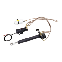
3.3Hydraulicrammounting
Mountthehydraulicramassecurelyaspossibletoensureit
performsreliablyandremainscorrectlyaligned.
•Beforemountingthehydraulicram,refertotheguidanceprovided
inthe2.8Locationandmountingrequirementssection.
•Drill4holesforthemountingfoot(eachholemustbe8.8mm
(0.34in)diameter).
•Attachthemountingfoottotheappropriatepartofyourvessel
usingthesuppliedbolts,washers,andnuts.
•Tightentheboltsto17Nm(12.5lbft)torque.
3.4Steeringsystemconnection
Therodendofthehydraulicrammustbeconnectedtothevessel’s
tillerarmorrudderquadrant.
Beforeconnectingthehydraulicramtothesteeringsystem,ensure
thatyourvessel’stillerarmorrudderquadrantcancopewiththe
peakthruststatedintheTechnicalSpecication.
Useoneofthefollowingmethodstoattachthepushrodtothe
rudderstock:
•Independenttillerarm—thisistherecommendedmethod.
•Steeringlinkagetillerarmorrudderquadrant—insome
cases,youmaybeabletoattachthepushrodtothesame
tillerarmorrudderquadrantusedbythemainsteeringlinkage.
Consultthesteeringmanufacturerbeforeyoumodifytherudder
quadrant.
Thefollowingdiagramillustratestheconnection:
1.Tillerpin.
2.Tillerarmorrudderquadrant.
Attachingtherodend
Note:Thesuppliedtillerpinissuitableforaquadrantthickness
of12mm(0.47in)to16mm(0.63in).
1.Attachthetillerpintothetillerarm,asshowninthediagram
below:
24
HydraulicLinearDriveInstallationinstructions
 Loading...


