i.Insertthetillerpinthroughthetillerarmholesothatthe
angeremainsabovethearm.
ii.Ensurethetillerpinisatighttinthetillerarm.Raymarine
recommendstheuseofasuitableadhesivearoundthetiller
pin.
iii.Usethesuppliedlockwasherandfullytightenthelocknutto
27Nm(20lbft).
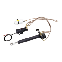
2.Attachtherodendtothetillerpin,asshowninthediagram
below:
i.Placetherodendontothetillerpin.
ii.SecurewiththesuppliedwasherandR-clip.
1.R-clip.
2.Washer.
3.Rodend.
4.Flange.
5.Tillerarm.
6.Lockwasher.
7.Locknut.
8.Tillerpin.
9.Holediameter,asfollows:
•Type2:12.2mm(0.48in).
•Type3:20mm(0.78in).
Note:Itmaybenecessarytodrillaholeinthetillerarm.Thehole
mustbeofthediameterspeciedabove.
Steeringcheck
Oncethehydraulicramismountedyoumustperformasteering
checktoensuretheramhasbeenmountedcorrectly.
Turnyourvessel’ssteeringwheelfromhardovertohardoverand
checkthefollowing:
•Angularmovementoftheballendttingislessthan10degrees
fortheType2drive,or5degreesfortheType3drive.Ifthis
limitisexceededthedrivewillcatchonthetillerarmorrudder
quadrantandtheballjointwillbind.
•Ensurenopartofthedriveunitfoulsyourvessel’sstructurewhen
thepushrodmovesinandout.
•Ensurethatthetotalruddermovementislimitedto+/-35degrees
bythesteeringsystemendstops,ratherthanthelineardrive’s
endlimits.
Mounting
25
 Loading...