4.2Connectionsoverview
Y
ourproductissuppliedpoweranddatausingtheSea Talkng®connectorlocatedontheback
oftheunit.
ConnectorConnections
•Sea
Talkng®backboneusingaSeaTalkng®spurcable.
•NMEA2000backboneusingSeaTalkng®toDeviceNetadaptorcable
(A06045)
•SeaTalk®backboneusingaSeaTalk®toSeaTalkng®adaptorcable(A06073)
Foralistofavailablecablesreferto:p .49—Sparesandaccessories
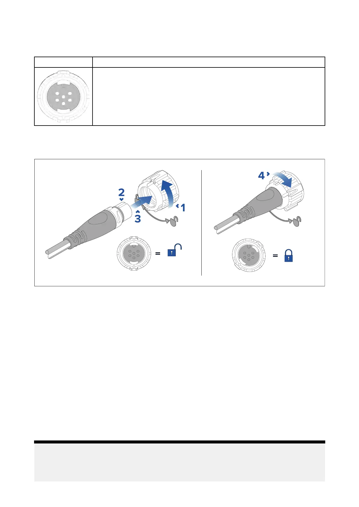
ConnectingSeaTalkng®cables
1.R otateyourproduct’sSeaTalkng®connectorlockingcollarcounterclockwise,sothatthe
connectorisintheunlockedposition.
2.Ensurethecable’sconnectoriscorrectlyoriented(groovepointingup).
3.Fullyinsertthecableconnector..
4.Rotatethelockingcollarclockwise(2clicks)untilitisinthelockedposition.
4.3SeaTalkng®powersupply
Y ourproductissuppliedpowerviatheSeaTalkng®backbone.
ASea Talkng®backbonerequiresasingle12Vdcpowersupply.Powercanbesuppliedtothe
SeaTalkng®backbonebyoneofthefollowingmethods:
•
(1)
directconnectiontoa12Vdcbattery
•connectionviaa12Vdcdistributionpanel
•
(2)
viaanAutopilotControlUnit(ACU)(notACU-100or150),oranSPXcoursecomputer(notSPX-5)
thatisconnectedtotheSea Talkng®backbone.
•for24Vvessels,viaa5amp,regulated,continuous24Vdcto12Vdcconverter
Note:
•
(1)
Thebatteryusedforstartingthevessel’ sengine(s)shouldNOTbeusedtopowerthe
SeaTalkng®backbone,asthiscancausesuddenvoltagedropswhentheenginesarestarted.
•
(2)
TheACU-100,ACU-150orSPX-5productscannotbeusedtopowertheSeaTalkng®backbone.
Connections
27
 Loading...