A B
2
1
D1194 6-2
P OWE R
P OWE R
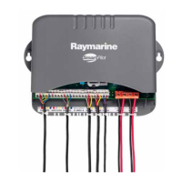
1.Coursecomputerconnectionpanel
2.Powerdistributionpanel
Powerconnectioncolors
ColorDescription
ARed
Powerin+ve(12/24V)
BBlack
Powerin-ve(0V)
Driveconnection
Thedriveconnectstotheconnectionpanelofthe
coursecomputer.
MADE IN HUNGARY
GROUND
P OWER, 1 5 AMP
12 V
24 V
FLUXGATE
RUDDER
CLUTCH
SLEEP
P OWER
B
MOTOR
A
1.Clutch(notalldriveshavethisconnection)
2.Motor/drive
Clutchconnectioncolors
ColorDescription
ARed
Clutch+ve
BBlue
Clutch-ve
Clutchvoltageswitch
Ifthedrivehasaseparateclutchconnectiontothe
coursecomputer,youmustensurethattheclutch
voltageswitchissetcorrectly.
Note:Theclutchvoltagemaybedifferentfromthat
ofthedriveitself,forexampletherangeofboth12
and24VRaymarinedrivesallhavea12Vclutch.
Solenoiddriveconnection
GR OUND
P OWE R
S OLENOID S OLENOID
A B
12 V
24 V
D10 456 -2
1
2
3
4
5
1.Electronicsteering/joglever(ifrequired)
2.Back-feedprotectiondiodes(ifusingaelectronic
steeringorjoglever)
3.Driveout.
4.Drivereturn
5.Solenoidvalves(withdiodesacrossspoolvalves)
Carepoints:
•Ifanelectronicsteeringorjogleverisused,tdiodes
(suggestedtype:1N4004)inlinewiththesolenoid
outputstopreventback-feedingthecoursecomputer.
20
SPX10,SPX30,SPX-SOL
 Loading...