Chapter 2, Fluxgate Compass Transducer
ST40 Instruments Service Manual 83149-2 3-5
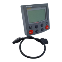
Fluxgate Compass
Transducer
Chapter 2. ST40 Fluxgate Compass Transducer
Functional test
Disconnect the Fluxgate Compass from the instrument and check continuity as
follows:
Cable colour Resistance
Screen to blue < 10 ohms
Red to green < 5 ohms
Red to yellow < 5 ohms
Red to screen Open circuit
Magnetic deviation
The Fluxgate Compass requires careful siting to achieve optimum performance. The
instrument software is able to correct the compass for most deviating magnetic fields
present when the linearisation procedure is carried out. Any further deviation
introduced after linearisation, will introduce an error between the Fluxgate Compass
and the ship’s compass. This can be removed by carrying out the linearisation again.
If the displayed deviation is greater than +/– 15 degrees the Fluxgate should be
resited. For installation and calibration information, refer to the ST40 Compass
Instrument Owner’s Handbook.
Note: The linearisation procedure should always be carried out if the Fluxgate
Compass has been exchanged, or moved from its original mounting position.
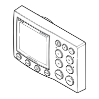
Disassembly/reassembly
D4519-2
1 2
7
3 6 5
9
1. Cover
2. Seal
3. Pivot retaining screw (x2)
4. Bracket
5. Pivot sub-assembly
6. Fluxgate sub-assembly
7. Body
8. Body screw (x4)
9. Cable
Red
Yellow
Green
Blue
Screen
Connector Wiring Detail
4
Hot melt glue
Cable tie
8
Fluxgate Compass Transducer Exploded View

 Loading...