Chapter 1: Overview 9
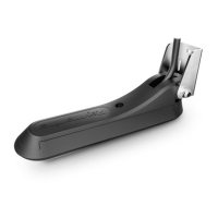
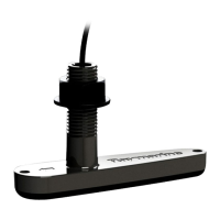
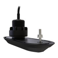
Figure 1-2: Transom Mount Transducer - Quick-release Bracket
• Onaboatwithafiberglasshull,theleadingedgeof thetransducer
shouldextend 1/8" (3.2 mm) to 1/4" (6 mm) below the bottom
edgeofthehullasshowninFigure1-3. Onanaluminumhull,the
transducer should extend a bit more – 1/4" (6 mm) to 3/8" (9 mm)
• If the boat will be trailered, be sure the transducer will not hit any
rollers,bunks or fittings on the trailer.
Figure 1-3: Transom Mount Transducer - Vertical Position
D4872-2
Transducer in
released position
Allow a clearance of
at least 254 mm (10 in)
No!No!No!
Average transom angle -
no wedge necessary
Vertical transom -
place wedge this way
Sloping transom -
place wedge this way
2° to 5°
2° to 5°
For fibreglass hull 1/8 to 1/4 in (3.2 to 6 mm)
For aluminium hull 1/4 to 3/8 in (6 to 9 mm)
The bow of the transducer
is above the bottom of the
transom, creating cavitation.
Rivets on the hull are
creating bubbles. Lower
the transducer a bit.
The rear of the transducer
is too high, creating
cavitation.
D4873-2
2° to 5°
 Loading...