Do you have a question about the Raytheon RayChart 601XX and is the answer not in the manual?
Details about the RAYCHART 601XX system, its features, and C-Map NT cartography.
Critical advisory regarding the device's use as a navigation aid and user responsibility.
Explains the purpose and structure of the operation manual's sections.
Explains installation requirements for EMC directive conformance on EC vessels.
Instructions for safely unpacking and inspecting the RAYCHART 601XX unit and its accessories.
Lists all items included in the RAYCHART 601XX package for verification.
Details optional accessories for customizing the RAYCHART installation for radar integration.
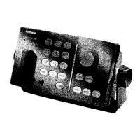
Provides guidance on selecting a location and mounting the RAYCHART controller.
Factors to consider when choosing a mounting location for the controller unit for protection and ease of use.
Step-by-step instructions for mounting the controller unit using the yoke bracket.
Procedures for flush mounting the controller unit into a console using kits.
Details the rear panel connections and electrical hookups for the RAYCHART unit.
Information on DC power requirements and connection for the RAYCHART unit.
Instructions for connecting the RAYCHART to the XX Radar display unit via interface cable.
Steps for connecting the RAYCHART to an RL-9/ST-50 Radar display using an adapter kit.
Information on connecting RAYCHART to X-Series radar displays using an adapter kit.
How to connect and use an optional GPS sensor for position data input.
Details on connecting the RAYCHART to a SeaTalk bus for data interchange.
Explains the NMEA data input/output ports (Port A and Port B).
How to connect a serial printer for hard copy output of screen data.
Procedures for assembling the 6-pin and 3-pin connectors for data and SeaTalk.
Recommended grounding methods for clean, noise-free signals.
Procedures for configuring the Raychart after initial installation.
How to program the Raychart to match the connected radar display type.
Choosing the correct input data format for the Navaid for data reception.
Selecting the data output format for compatibility with other devices.
Choosing between Port A (NMEA) and Port B (GPS) for data input.
Verifying the operation and status of the connected GPS sensor.
Overview of the RAYCHART 601XX operation, emphasizing ease of use and familiarization.
Description of the two main areas of the display: Chart and Navigation Data panel.
Explanation of the front panel layout, keys, and trackpad assembly.
Details the POWER, BRIGHT, and DIM keys for display and keyboard control.
Instructions for turning the RAYCHART on/off and the startup self-test sequence.
Controls the brightness of the charting presentation on X Series radar displays.
Adjusts the backlighting level for the front panel keyboard.
Covers controls for chart manipulation like Trackpad, ZOOM, PAN, and HOME keys.
Explains the use of background charts and C-Map cartridges.
How to locate and display charts from installed C-Map cartridges.
Used to change chart scale and display levels for detailed viewing.
How to use the trackpad to control the cursor and explore the chart.
Accessing and displaying information about navigation aids and points.
Explains the two cursor modes: Cursor Mode and Home Mode.
Displays cursor L/L, bearing, and distance from own ship.
Locks cursor to own-ship symbol and displays data to waypoint.
Centers the chart on a specific point without changing scale.
Allows panning over large geographic distances to specific Lat/Long.
Concepts of Waypoints and Route Plans for navigation planning.
Selects the next waypoint destination and initiates GOTO waypoint function.
Accesses menus for making, editing, listing, and clearing route plans.
Steps to remove an existing route plan from active memory.
Procedure for creating a new route plan by adding waypoints sequentially.
Method for entering waypoints by manually inputting Latitude/Longitude.
Instructions for modifying existing route plans, adding or inserting waypoints.
Displays a tabular list of route plan contents, distances, and bearings.
How to print route plans or chart screens using a connected printer.
Activates and follows a route plan in forward, reverse, or auto/manual mode.
Sets the direction of route following (Forward, Reverse, OFF).
Selects whether to follow internal or external route plans.
Chooses automatic or manual switching between waypoints.
How to skip waypoints in a route plan without deleting them.
Describes the operation of the Function keys (MARK, EVENT, TRACK, etc.).
Allows placing marks on the chart with different symbol types.
Placing marks directly on the chart using the cursor.
Marking a point by entering its bearing and range from the current position.
Placing or editing marks using direct Lat/Long coordinate entry.
Used to place marks at the ship's position, typically for fishing spots.
Accesses the TRACK menu for recording and displaying vessel track history.
Recalls and displays previously saved track lines.
Selects patterns and starts recording the vessel's track.
Configures the time or distance interval for recording track points.
Deletes the currently recorded track line from active memory.
Accesses memory functions for saving and replaying navigation data.
Explains the different memory areas: Internal, User C-Card, and Active.
Displays files stored in the RAYCHART's internal memory.
Navigating memory menus and creating file labels for saved data.
Procedure for saving navigation data to files.
Saves a recorded track line to memory.
Transfers saved files from memory to the active display.
Saves route plans or marks to a removable User Data Card.
Erases Marks or Events from the active display memory.
Procedure for erasing specific files from memory.
Accesses the NAV Display menu for configuring data panel readouts.
Switches the RAYCHART Cartography screen on/off on the radar display.
Activates Man Overboard mode for recording position and tracking.
Measures range and bearing between two points on the chart.
Accesses the main menu for various setup functions.
Controls the display of various layered data on the cartographic display.
Controls display of land features like coastlines, rivers, and landmarks.
Controls display of marine data like depth areas, spot soundings, and units.
Controls display of naval aids like ports, lights, buoys, and tracks.
Configures display of chart names, compass, objects, and info level.
Configures coordinates, boundaries, smooth scroll, and plotter mode.
Accesses seven setup functions for the RAYCHART.
Sets the distance for the waypoint arrival alarm.
Turns the clock display on/off and sets the unit's internal time.
Manually adjusts the own-ship symbol position on the chart for accuracy.
Turns on/off display of Heading and Course vectors.
Chooses between Magnetic or True bearing display.
Sets chart rotation and the threshold for chart redraws.
Accesses installation parameters like language and data formats.
Sets the display language for menus and readouts.
Selects the input data format accepted from external navigators.
Selects the data output format for compatibility with other devices.
Selects data input source between NMEA Port A or GPS Port B.
Reports the status of connected GPS sensors.
Displays information from vessel's SeaTalk instruments.
Lists various SeaTalk data digitally, including depth, speed, and wind.
Displays a graph of Depth versus Time for the last 12 hours.
Shows a graph of True Wind direction and speed versus time.
Displays a graph of Speed through water and SOG versus time.
Logs and displays position, CMG, and DMG every half hour.
Simple maintenance tips to ensure satisfactory operation and prevent premature failures.
Built-in operations for analyzing system performance, reserved for technicians.
Accesses the System Unit Test screen for various diagnostic tests.
Checks integrity of external connections and reviews data input.
Verifies data readability from the C-CARD cartridge.
Tests each key for proper electrical contact and response.
Resets the RAYCHART to factory default settings, erasing memory.
Adjusts chart positioning by compensating for horizontal frequency differences.
Information on the internal battery, its lifespan, and recommended replacement.
Identifies common messages for C-Map cartridge failures.
Provides a chart to diagnose and resolve common RAYCHART symptoms.
A table listing replaceable parts and their corresponding part numbers.
Visual guide to symbols used in NT cartography on C-Map charts.
| Display Type | LCD |
|---|---|
| Update Rate | 1 Hz |
| Interface | NMEA 0183 |
| Operating Temperature | -15°C to +55°C |
| Power Source | External |
| Channels | 12 |
| Accuracy | 15 m (RMS, SA off) |