19
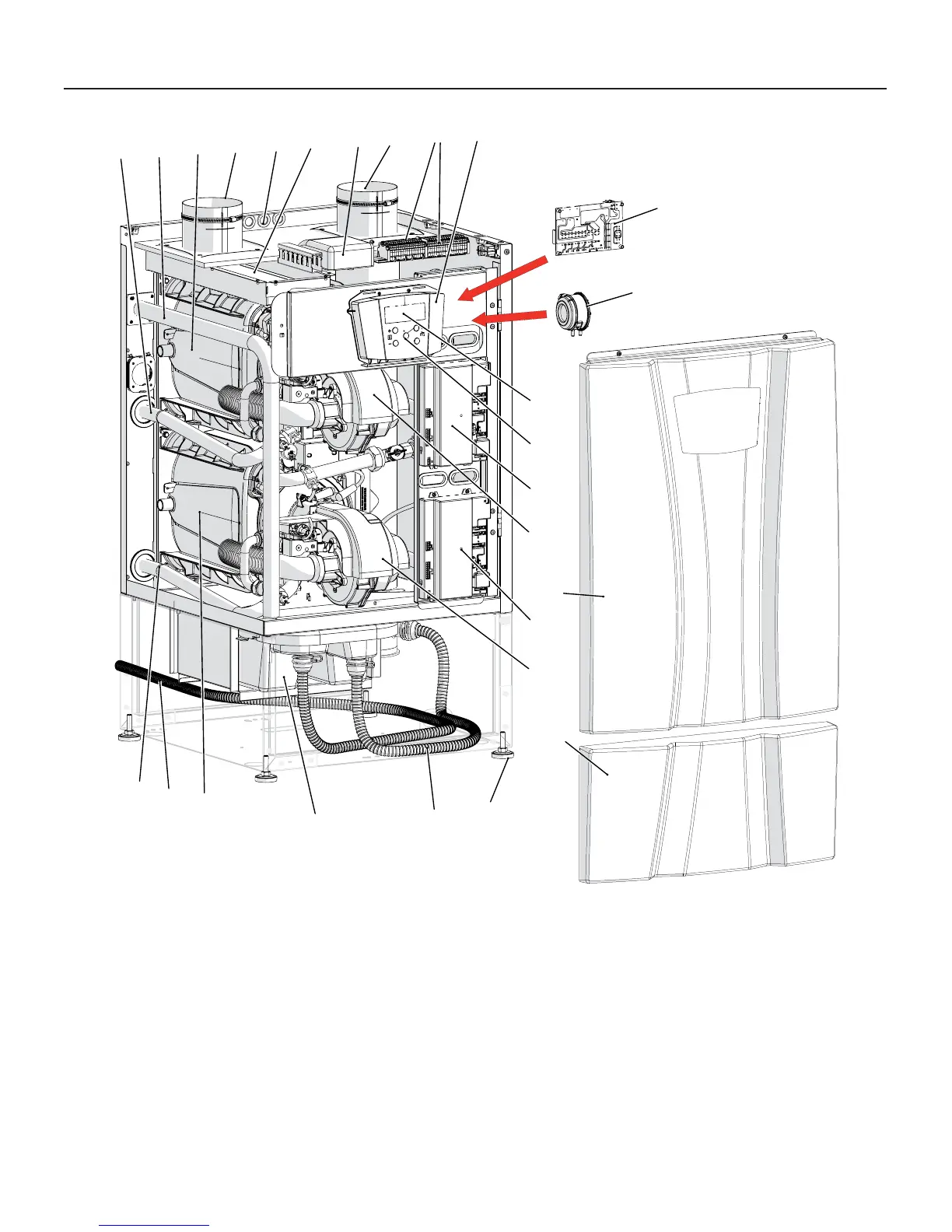
Figure 3-5 Main components for models 399 and 500
3 - MAIN COMPONENTS
1 - Levelling feet
2 - Condensate hose that coming from heater’s fl ue exhaust
3 - Condensate neutralizer box
4 - Heat exchanger
5 - Condensate discharge hose
6 - Gas inlet pipe
7 - Water Supply pipe
8 - Heat exchanger
9 - Air inlet connection
10 - Electrical cable passages
11 - Air fi lter
12 - Flue exhaust connection
5
10
12
7
7
4
1
8
24
9
6
25
2
3
11
14
20
18
40
13
40
15
17
16
21
19
020010.01.002
13 - Modbus, 0-10Vcc, and cascade communication board
14 - Electrical terminals
15 - Control panel cover
16 - Display
17 - Control keys
18 - “Burner 2” power control board
19 - Front cover
20 - “Burner 1” (Master) power control board
21 - Bottom front cover
 Loading...


