20
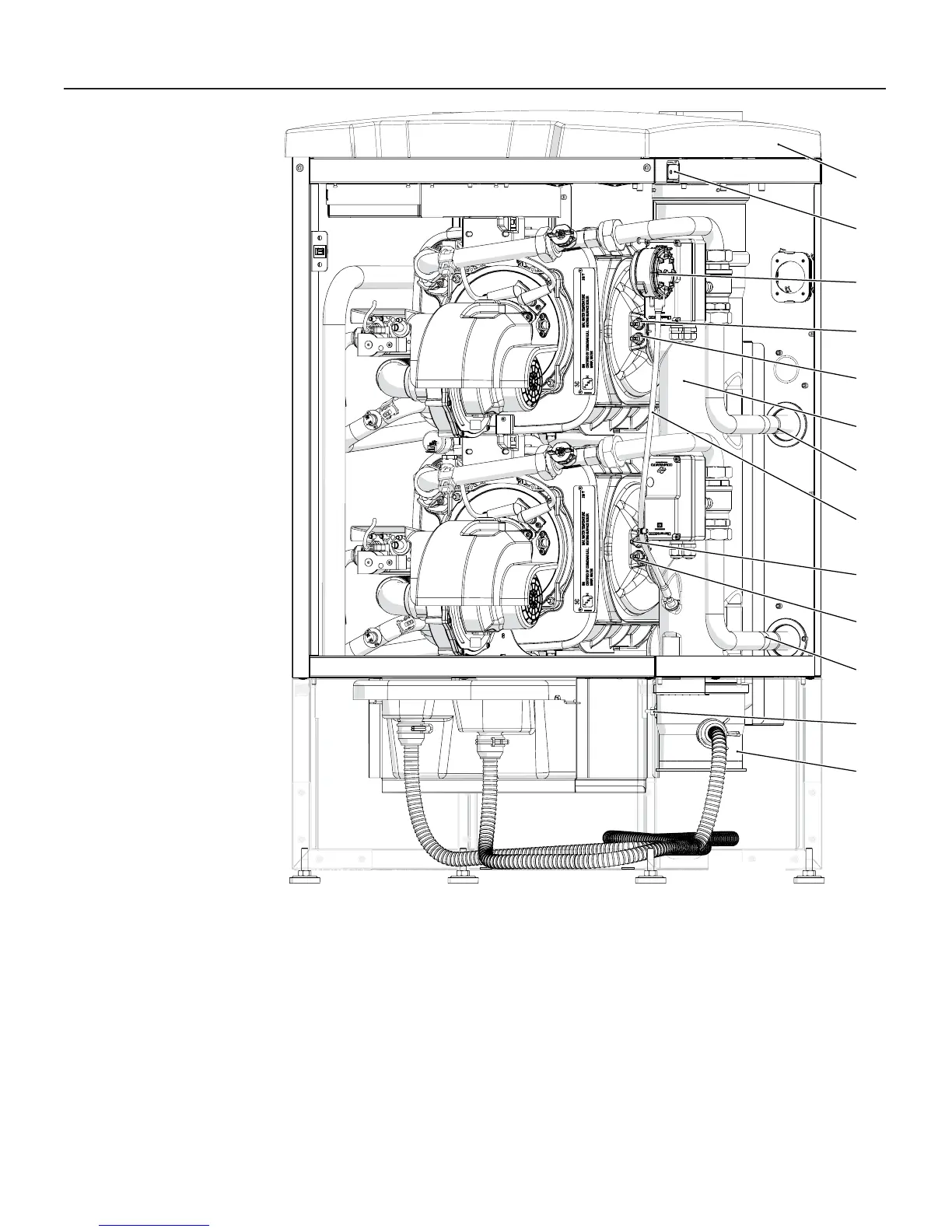
3 - MAIN COMPONENTS
22 - Top cover
23 - Main electrical switch
24 - Flue blocked pressure switch
25 - Electrical Board
28 - Burner unit fl ue gas temperature sensor (Blue color connector)
29 - Burner unit high limit fl ue gas temperature fuse (Red color
connector)
30 - Flue gas exhaust manifold
31
33
28
28
22
29
34
31
30
32
23
24
29
020010.01.003
31 - Water Return pipe
32 - Flue blocked pressure switch pipe
33 - Condensate blocked drain magnetic switch
34 - Flue gas manifold cap
Figure 3-6 Main components for models 399 and 500
BURNER 2
BURNER 1 (Master)
 Loading...


