The provided document is an installation manual for the IRONCLAD Perimeter Security System by RBtec. This system is designed to detect intrusions along a fence line and provides an alarm output.
Function Description
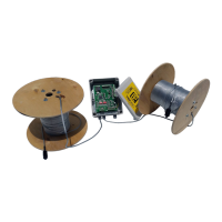
The IRONCLAD system is a fence-mounted sensor system that detects attempts to climb, cut, or otherwise breach a fence. It consists of a sensor cable, an End-Of-Line Termination Unit (MCTR), and a Local Processing Unit (LPU-400). The sensor cable is attached to the fence and detects vibrations caused by intrusion attempts. These signals are then processed by the LPU-400, which can trigger an alarm. The system is designed to filter out false alarms caused by natural fence movement due to weather.
Important Technical Specifications
Sensor Cable:
- Length per zone: Up to 1000ft (300m) per zone.
- Installation: Must be attached to the internal (protected) side of the fence, ideally in the middle and running parallel to the ground within the chain link's low point groove.
- Ties: Attached every 12 inches (30 cm) using IRONCLAD ties (recommended for durability) or outdoor UV plastic tie wraps/zip ties. Ties must be vertical, securely tightened to prevent sliding, but not over-tightened. White zip ties are not recommended.
- Around Poles: A "drop loop" of 2-3 fingerbreadths (2.5 - 4 inches) should be created around poles to allow free movement and prevent false alarms from natural fence movement. The cable should not be run between the pole and the fence.
- Stripping: Requires proper wire strippers; burning the coating is prohibited as it harms detection capability. All wire strands must remain intact.
End-Of-Line Termination Unit (MCTR):
- Purpose: Terminates the sensor cable at the end of each zone. Essential for zone functionality; a zone will remain in alarm without it.
- Components: Cover screws, push terminals, case cover, 1M (1000k) Ohm resistor, holding pin.
- Assembly: The sensor cable's clear wire is connected to the push terminals along with the resistor. The terminal is then pressed onto a holding pin for secure fastening. The case is closed in a specific sequence (1, 5, 4, 3, 6, 2).
- Mounting: Mounted at the very end of each zone with the cable input facing the ground.
- Pre-installation check: Verify no shorts between sensing wire and GND wire.
Local Processing Unit (LPU-400):
- Models: LPU-400 (general) and LPU-402 (specific wiring example).
- Power Input (DC): 12-24VDC. AC power is explicitly prohibited.
- Chassis Ground: Connect to a true ground to protect against surges and lightning.
- Sensor Cable Inputs: Dedicated inputs for Zone 1 (Z1) and Ground (GND).
- General Inputs: 4 general inputs for any sensors (INPUT 5, 6, 7, 8).
- Alarm Output Terminals: Dry contact relay alarm outputs (Z1, Z2, Z3 with corresponding GNDs). Each input has a dedicated output (e.g., Zone 1 triggers Relay 1). Outputs are Normally Closed (NC) by default but can be changed to Normally Open (NO) via LPU Calibration software.
- Power Outage Alarm: Dedicated relay output for power cut/drop indication.
- Configuration Board: Includes a tamper switch.
- Indicator Lights (LEDs):
- Red LED (Sensing Indication): Must be solid at number 1 when the fence is not touched. Flicker or other numbers indicate "noise" and potential false alarms. Noise can be caused by loose connections, resistance outside 0.95-1Mohm, or lack of sensor ground wire.
- Green LED (Active Zone): At least one green LED must be lit per active zone.
- Power LEDs: All power LEDs (indicated on slide 17) must be on.
- Alarm Indication/Relay Latched: Indicates an active alarm.
- USC-C For Calibration: USB-C port for calibration.
- CPU Power Indicator LED: Indicates CPU power status.
- Power Interface Operation Indicator LED: Indicates power interface status.
- Voltage Input Indicator LED: Indicates voltage input status.
- Voltage Passes the Surge Protection of the Surge Protection: Indicates surge protection status.
Usage Features
Installation Area and Fence Condition:
- Preparation: Clear the fence and immediate area of overhanging branches, shrubbery, bushes, etc.
- Obstructions: Ensure no objects (trash, loose signs) are attached to, rattling on, or interfering with the fence.
- Fence Condition: Best performance on a fence that is fully intact, straight, under tension, and free of obstructions. Signs should be securely fastened.
Sensitivity Level Adjustment:
- Process:
- Enter setup mode by clicking "ENTER."
- Green LED in Zone 1 blinks.
- Select zone using "LEFT" and "RIGHT NAVIGATOR" buttons.
- Adjust sensitivity using "UP" and "DOWN" buttons.
- Press "ESC" to exit calibration.
- Sensitivity Setting Jumper: Allows selection between "Low Sensitivity" and "High Sensitivity."
- Reset: Board can be reset after every change.
- Disarmed/Disabled: If both sets of LEDs are off, the system is disarmed. Press "ENTER" then "UP" to enable.
- Power Saving: Sensitivity lights turn off after 1 minute to save power; other green LEDs remain on.
Swing Gate Protection:
- MCTXT: Used for swing gate protection.
- Cable: Non-sensitive RG6 Direct Burial cable under the gate in waterproof conduit.
Maintenance Features
Warranty:
- Extended Warranty: 3 years on the Processor and Cable. Requires scanning a QR code or visiting Warranty.rbtec.com.
- Initial Setup: Scan QR code before installation to activate the warranty.
Troubleshooting (Default LPU Processor Settings):
- All power LEDs on slide 17 are on.
- No alarms indicated on RLY outputs.
- Only 1 red LED shown per zone.
- At least 1 green LED lit on each active zone.
Sensitivity/Alarm Testing:
- Method: ONLY by tapping on the fence (simulating knocking on a door or using a screwdriver/wrench to simulate wire cutters). Pulling, pushing, or shaking the fence is incorrect.
- Procedure:
- Tap the fence; if detected, the red LED moves from 1 to 6. Lower sensitivity until only a hard tap causes the red LED to reach 6 and trigger the alarm LED.
- Once this level is reached, raise sensitivity by 1 level to achieve the detection level.
- Test by simulating a person climbing or a cut (tap twice with a heavy metallic tool).
Periodic Testing:
- Recommended monthly to quarterly system tests to verify proper operation.