iiiiiiiiiiiiiiiiiiiiiiiiiiiiiiiiiiiiiiiiiiiiiiiiiiiiiiiiiiiiiiiiiiiiiiiiiiiiiiiiiiiiiiiiiiiiiiiiiiiiiiiiiiiiiiiiiiiiiiiiiiiiiiiiii
RCA W0-33A Cathode-Ray Oscilloscope
iiiiiiiiiiiiiiiiiiiiiiiiiiiiiiiiiiiiiiiiiiiiiiiiiiiiiiiiiiiiiiiiiiiiiiiiiiiiiiiiiiiiiiiiiiiiiiiiiiiiiiiiiiiiiiiiiiiiiiiiiiiiiiiiiii
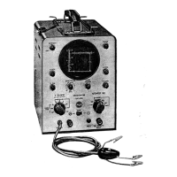
NORMAL
CIRCUIT
HORIZONTAL
OVERALL
FREQUENCY
EFFECT
ON
HORIZONTAL
FAULT
PULSE
RESPONSE OF
PICTURE
PULSE
DISTORTION
RECEIVER
J\
V
1
NORMAL
PICTURE
CIRCUIT
~
NORMAL
r-
1\
LOSS
OF
HIGH
A.
~
LOSS
OF
FREQUENCIES
--.I
PICTURE
DETAIL
I--
EXCESSIVE
J)
V
FINE
VERTICAL
HIGH
- FREQUENCY
BLACK
& WHITE
RESPONSE,
STRIATIONS
FQL-
NON-LINEAR
LOW I
NG
A SHARP
PHASE
SHIFT
--l
"'-
CHANGE
IN
PIC-
TURE
SHADING
LOSS
OF
LOW
CHANGE
IN
SHA-
FREQUENCIES
1\
V
1
DING
OF
LARGE
(IN
THE
RANGE
PICTURE
AREAS;
ABOVE
15
OR
-
I-"'-
SMEARED
PIC-
20
KC)
TURE.
PICTURE
SOUND
CARRIER
CARRIER
Figure
6.
Sync-pulse
distortion
(Continued
from
page 11)
1.
Tune
the
television receiver to a television
signal.
2. Rotate
the
INTENSITY
control on
the
WO-33A
clockwise.
Set
the
SYNC control
to
"INT". Set
the
INTENSITY
and
FOCUS
controls for
the
desiredof
brightness
and
best
focus.
3.
Connect
the
WG-349A
probe
and
cable con-
nector to
the
V
INPUT
connector. Connect
the
ground
lead
to
the
receiver chassis. Connect
the
yellow
probe
clip to
the
grid terminal of the picture
tube
socket.
It
is
not
necessary
that
the
picture
tube
be
connected
for this test.
4. Set
the
V
RANGE
switch
and
the
V CAL
control for a
pattern
of convenient height.
5.
To
obtain
the
horizontal-sync pulse on the WO-
33A screen, set
the
H/SWEEP
SEL
control to
the
1500 • 15 Kc position. Adjust
the
SYNC/PHASE
control, if necessary, to
obtain
lock-in on
the
sync
pulse,
and
adjust
the
SWEEP
VERNIER
control
so
that
two
complete
waveforms
appear
on the
screen. To obtain
the
vertical-sync pulse, set the
HI
SWEEP
SEL
to
the
15
• 150 position. Readjust the
SWEEP
VERNIER
for two complete waveforms.
The
pulses should resemble those
shown
in
Figures
3
and
4.
Alignment
The
process of television-receiver alignment
probably requires a greater
amount
of skill
and
understanding on
the
part
of
the
service technician
than
does any
other
service function. Before
under-
taking alignment,
it
is
important
that
the
technician
recognize
the
symptoms of a misaligned receiver.
The
order in which various sections of the tele-
vision receiver
are
aligned may differ
between
split-
channel sound
and
intercarrier types. Different re-
ceivers of one system may also differ in
the
order
of alignment.
In
all cases, however,
the
alignment
order given
by
the
manufacturer in his service notes
should
be
followed.
For
these reasons, it
is
not feasible to present a
general alignment procedure applicable to all re-
ceivers. Some general precautions
and
suggestions
for using
the
WO-33A Oscilloscope, however,
are
provided below to aid
the
television technician in
servicing a receiver.
• 14 •
iiiiiiiiiiiiiiiiiiiiiiiiiiiiiiiiiiiiiiiiiiiiiiiiiiiiiiiiiiiiiiiiiiiiiiiiiiiiiiiiiiiiiiiiiiiiiiiiiiiiiiiiiiiiiiiiiiiiiiiiiiiii RCA WO-33A Cathode-Ray Oscilloscope iiiiiiiiiiiiiiiiiiiiiiiiiiiiiiiiiiiiiiiiiiiiiiiiiiiiiiiiiiiiiiiiiiiiiiiiiiiiiiiiiiiiiiiiiiiiiiiiiiiiiiiiiiiiiiiiiiiiiiiiiiiiii
Receiver alignment requires, in addition to
the
WO-33A, a sweep generator, a marker generator of
crystal accuracy,
and
a
vacuum-tube
voltmeter.
An
RCA
WR-59
or WR-69-series Sweep Generator, an
RCA WR-39, WR-99 or
WR-89
Calibrator,
and
an
RCA VoltOhmyst"', such as
the
WV-77, \VV-87,
WV-97,
or
WV-98 are recommended.
Tuner
Alignment
-
When
preparing
for
tuner
alignment,
the
manufacturer's recommendations
should
be
followed closely.
If
the
tuner
has test
points for connecting
equipment,
the
test
points
should
be
used.
The
oscilloscope test point is usually
connected internally to
the
mixer grid circuit
where
a
demodulated
signal is present.
The
output
cable of
the
sweep generator should
be
connected
to
the
antenna
input
connectors.
The
ground
lead
of
the
W
0-33A
should
be
clipped
directly
to
the
tuner
shield to minimize
hum
pickup
on
the
sweep
trace,
and
the
WG-349A blue clip
should
be
connected to
the
mixer grid -circuit test
point.
If
no
test point
is
provided,
the
WG-349A
may usually
be
connected to
the
grid circuit through
a 5,000
to
10,000-ohm composition resistor.
It
is
important
that
the
WG-349A
be
connected
directly to
the
proper test point or, if a series resistor
is
used,
that
the
lead
length
between
the
probe
clip
and
the
mixer grid circuit
be
kept
as short as
possible
to
prevent
hum
pickup
and
possible dis-
tortion of
the
tuner
curve
on
the
WO-33A.
Hum
pickup is evidenced
by
twisting of
the
base line
when
return-trace blanking is used on
the
sweep
generator. This precaution
is
necessary because of
the
high-gain level
at
which
the
WO-33A is operated
for
tuner
alignment.
The
INTENSITY
control should
be
turned
clock-
wise to
obtain
a trace of suitable brilliance.
The
vertical
gain
controls should
be
set for maximum or
near
maximum gain.
The
output
from
the
sweep
generator
and
marker calibrator should
be
set
at
a
low level to avoid over-loading
the
TV
receiver,
distortion of
the
sweep curve,
and
an
erroneous
picture
of alignment on
the
oscilloscope screen.
When
the
WO-33A
is
used
with
a sweep generator,
it is
important
that
the
two instruments
be
adjusted
so
that
blanking is correct
and
the
sweep of both
instruments
is
in phase.
If
the
phase
adjustment
is
not
properly
set before starting alignment,
the
sweep
0Trade Mark "VoltOlunyst" Reg.
U.
S.
Pat.
Off.
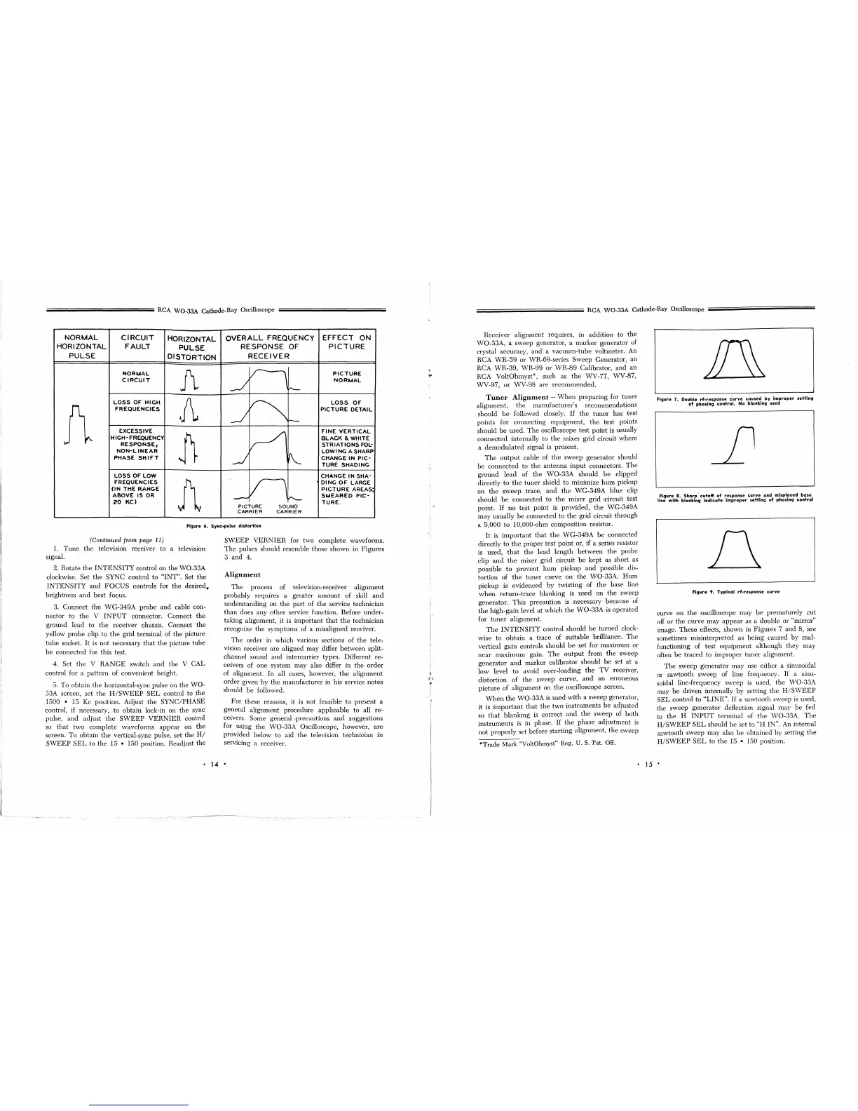
Fi9ure 7. Double
rf-response
curve
caused
by
improper
settinq
of
phasin9
control.
No
blanking used
Figure 8.
Sharp'
cutoff
of
response
curve
and
misplaced
base
line with blanking
indicate
improper
settin9
of phasin9
control
Figure
9.
Typical
rf-response
curve
curve on
the
oscilloscope
may
be
prematurely
cut
off or
the
curve
may
appear
as a double or
"minor"
image.
These
effects, shown in Figures 7 and 8,
are
sometimes misinterpreted
as
being caused by mal-
functioning of test
equipment
although they
may
often
be
traced
to improper
tuner
alignment.
The
sweep generator may use either a sinusoidal
or sawtooth sweep' of line frequency.
If
a sinu-
soidal line-frequency sweep
is
used,
the
WO-33A
may
be
driven
internally
by
setting
the
H/SWEEP
SEL control to
"LINE".
If
a sawtooth sweep
is
used,
the sweep generator deflection signal may
pe fed
to
the
H
INPUT
terminal of
the
\i\10-33A.
The
H/SWEEP
SEL
should
be
set to
"H
IN". An internal
sawtooth sweep may also
be
obtained by setting
the
H/SWEEP
SEL
to
the
15 • 150 position.
•
15
•
 Loading...