+ IN Priority
GND
– IN Priority
+ IN PGM
GND
– IN PGM
SWITCH PGM OFF
PILOTTONE
CHANNEL OK
BATTERY OK
+ 12V
CH 1
CH 2
OUT 2
AC 230V 6A
DC IN – + 48V 0 / 50 / 100
500W
0 / 50 / 100
OUT 1
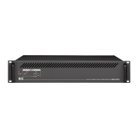
RüCKANSICHT DBA-SERIE
1. DC-Spannungsversorgungsklemme 24 V
2. Netz-Kaltgerätestecker
3. Lautsprecherausgänge 50 und 100 V
Bei500WBetrieb(DBA-500D)dieAusgänge1und2in
Serie schalten.
Verwenden Sie dafür auschließlich die 50V-Anschlüsse!
4. Symmetrische Eingänge (Input)
Bei500WBetrieb(DBA-500D) Input1und2gemein-
sam ansteuern. Die Lautstärkeregler (Vorderseite) müs-
sen dann auf die selbe Stellung eingestellt werden.
5. Switch Programm OFF
Schaltet den Programmeingang ab und aktiviert den Pri-
oritätseingang. Anzusteuern mit dem +12V Anschluss,
jeweilsfürCH1undCH2getrennt.
6. Eingang für Pilottonsignal
7. Störmeldeausgang (Funktionstörung)
Bei Defekt bzw. Funktionsstörung der Endstufe.
8. Störmeldeausgang (Notstromversorgung)
Bei fehlender Notstromversorgungsspannung
Verbinden Sie die NF Eingänge und Ausgänge mit den ent-
sprechenden Steckanschlüssen. Der Input kann symme-
trisch oder assymetrisch belegt werden. Bitte achten Sie auf
die richtige Belegung von Masse (geschirmte Leitung) und
Signal.
REAR VIEW DBA-SERIES
1. 24 V DC power supply terminal
2. IEC power inlet (cold condition)
3. Speaker outputs
50and100V,atDBA-500Dfor500Woperation-Output
1and2turnintoseries.
For this case use only the 50V-terminals!
4. Balanced inputs
At500Woperation(DBA-500D)actuateInput1and2
combined. The Volumecontroller (Front side) must turn
synchronal to same position.
5. Switch Programm OFF
Switch the Program input off and activate the Priority
input. Activate with +12V terminal for CH1 and CH2
separately.
6. Input for pilot tone signal
7. Failure indication output (malfunktion)
If notice of malfunction or defect of the amplifier.
8. Failure indication output (emergency power supply)
If emergency power supply is missing
Connect the AF inputs and outputs to the corresponding
plug-type connectors. The input can be used balanced un-
balanced. Please pay attention to the right of occupancy
mass (shielded line) and signal.
C1 6 8
2 754
REAR PANEL DBA-SERIES
 Loading...