3 Installation Procedures
3.1 Installation Preparation
3.1.1 1 pcs digital control power supply
3.1.2 Tools (Soldering iron, solder, Philips screwdriver, Wire stripping pliers)
3.1.3 A proper installation environment
3.2Installation Procedures
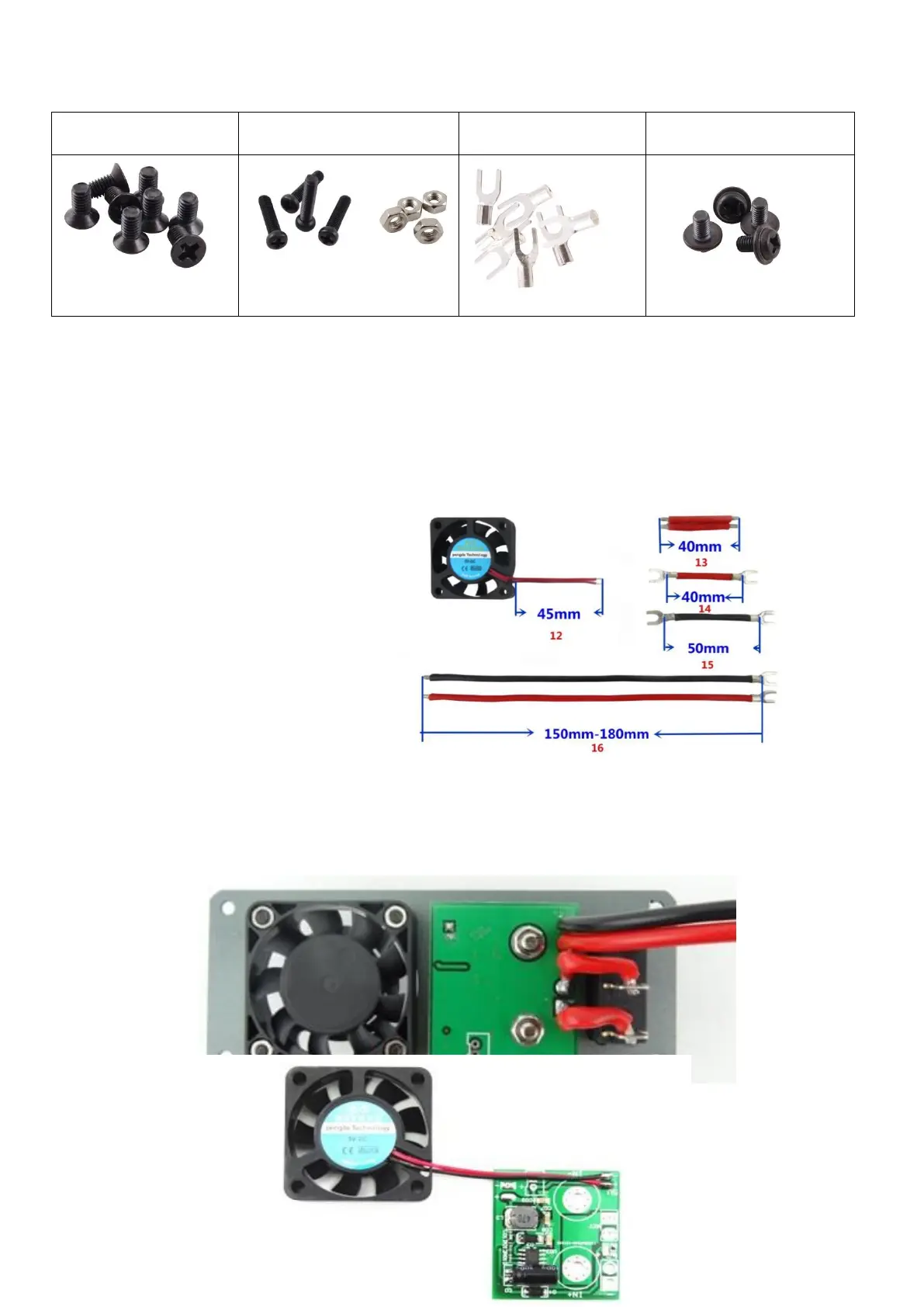
12- Fan line 45mm
13- Switch connecting line 40mm
14- Output positive line 40mm
15- Output negative line50mm
16- Input connecting line
150-180mm
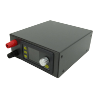
3.2.2 Install the input binding post and switch: put binding post and switch on slot at rear panel.
Install binding post according to rule that red is positive above, black is negative below; and
screw it tightly.
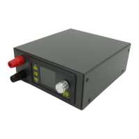
3.2.3 Install the fan: use the matched screw to fix. The one side attached label is install outward,)
3.2.4 Install fan
power supply
board:
3.2.4.1