Weld fan line on 5V place at fan power supply board (Note: can’t weld positive and negative
reversely).
3.2.4.2 Weld the input power supply line on the bonding pad on the upper left corner of board).
3.2.4.3 Install fan power supply board on the binding post (red is positive above, black is negative
below), then use the screw to fix them.
3.2.4.4 Use the prepared wire to weld the power switch on the kay place at fan power supply
board,
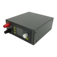
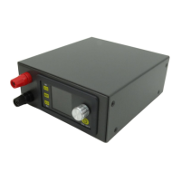
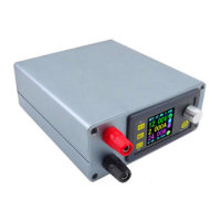
3.2.5 Install the output binding post, and use the output line with cold press connecting terminal
to connect input (red is positive above, black is negative below),and screw it tightly
3.2.6The product of this shell is divided into display module and power module, and the
installation process is:
3.2.6.1 Install the power supply module. Please put it on slot at front panel (when put it on slot,
strength will be proper to avoid the deformation).
3.2.6.2 Use the cable to connect display part with power part. Note the words LCD and KEY on
PCB to correspond to the same words on display part (the cable must go through under the PCB,
otherwise the capacitor will generate interface to effect it).
3.2.6.3 Install the power module according to the position of the four holes of the
lower cover, then use a matching screw to hold it .
3.2.6.4 The input positive and negative are respectively connected the port of the
power supply module IN+ and IN -.
3.2.7 After connecting, please power on to check it work or not (before power on, check
connection again)
3.2.8 Install the housing, note that the front end of the housing with an air inlet is installed in
the order of the front cover and then the front and rear panels.
3.2.9 This product is equipped with four transparent mats, the user can be
 Loading...