Contact ID messaging
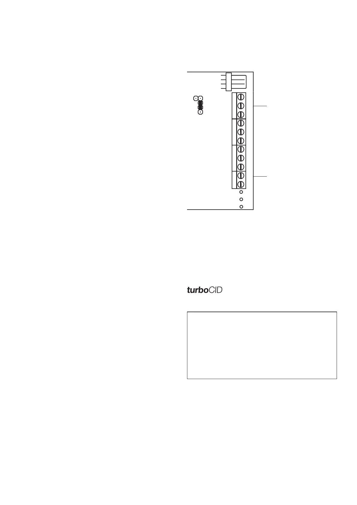
Connect the TIP and Ring terminals on the unit to the alarm
panel telephone interface and install jumper J17.
NOTE: the Contact ID account code is not sent as the unit
identifies itself via the Unit Reporting Name description.
Set custom CID messages
Understandable messages can be input to replace standard
Contact ID information.
CID message distribution
Unwanted messages can be limited by selecting the recipient
numbers which should receive messages in the telemetry list.
Select this option to simulate a dial tone for alarm panel.
Communication in this mode is substantially faster.
IMPORTANT
In order for the Contact ID interface to function, the
following settings on the alarm panel must be made:
Communications format Ademco Contact ID
Dial format Tone
Wait for dial tone Standard mode - no
TurboCID mode - yes
Central station no. (primary) 1234
SMS MESSAGING
General setup
Set unit time
The unit time is automatically set by the PC programming
software.
Unit reporting name
The reporting name is displayed in each SMS message to
identify from which unit the message is received.
Set the auto test period
Program the unit to send an 'auto test' SMS to the reporting
numbers once a day at a pre-set time. The feature also
prevents prepaid SIM cards being churned by the network
operator.
IMPORTANT
Due to the dual SIM feature, the TX-SMS should be
commanded periodically to use the redundant prepaid
SIM card so that it is not churned. See the remote
command guide on how to do this.
AC input monitoring
The input monitors and reports AC failures. To ensure correct
reporting, insert the DC bypass jumper when a DC voltage
reflecting the AC status is used. See diagram on first page.
AC status delay - The delay prevents unnecessary SMSs
caused by accidental unplugging and tripping or brownout.
Tripping/unplugging - standard setting 10 minutes
Brownout - standard 5 seconds
Default setting - 10 minutes
Battery monitoring
Low battery - reported at 10.8V
Critical battery - reported below 10V
Battery restore - reported when rises above 12V
Set vibration tamper monitoring sensitivity
A built-in vibration sensor sends a tamper SMS when
movement of the unit is detected. Set the sensitivity
appropriate to the installation from 0 - most sensitive to
255 - disabled.
Hardwired input messaging
Use direct connections to alarm panels or other low voltage
equipment (maximum input 16V DC).
Below 2V DC = low
Above 10V = high
Enter message recipient numbers
Enter up to 10 mobile numbers to which SMS messages will
be sent.
Enter the input messages
Input messages define the wording of SMS messages that are
sent when inputs are triggered. Set messages for both high
and low triggers. A blank field generates no message.
Configure message distribution
Use message distribution to avoid unwanted SMS messages
to selected users. Select which input messages are sent to
which of the 10 message recipient numbers.
CID jumper
J17
TIP
- DC Supply & RING
+ - IP1 IP2 IP3
IP4 IP5
IP6
IP7 TIP
AC
PWR
GSM
SYS
COMMS
Connect to
alarm panel
telephone interface
TM
 Loading...