Copyright © 2015
NB: Please read GSM Warnings and General Trading Terms and Conditions (including an indemnity) available from your supplier
I/O expander module
Sold separately
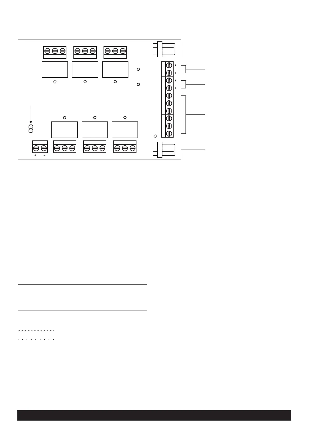
To SMX
Power supplied from SMX
Jumper on = 4/20mA
Jumper off = 0 - 10V
Relay 8
Relay 5
IP 8
Status
IP 9
Aux SerialSMX
NC NO CM
Relay 7
NC NO CM
Relay 4
Relay 6
NC NO CM
Relay 3
CM NO NC CM NO NC CM NO NC
Power rail
Input 9
Input 8
Optically isolated
POS NEG
8
A/D
9
Connection and power
Connect the port marked “SMX” on the I/O expander board to
the SMX unit’s serial interface using the serial cable supplied.
Power rail terminals
Power to the expander is supplied from the SMX unit via the
serial cable.
Power rail terminals are provided for peripherals. No outgoing
or ingoing power is present. Users can connect these
terminals to their own DC power source.
Relay switching
Relays on the I/O board function in the same way as the SMX
onboard relays and are programmed similarly in the
programming software. The relay specifications differ however.
SPDT I/O relays - 3A, 60VDC, 22VAC (non-inductive loads)
Lethal AC should not be switched via the relays.
Switch DC to an external contactor as a safety precaution.
LED status indications
Unit not detected by SMX
Connected
Optically isolated inputs
Recommended when interfacing to equipment where
dissimilar grounds are present (earth loop issues) or where
harmful voltage spikes and surges may be conducted or
induced into unit (e.g. electric fences).
Inputs are configurable and can support:
- Dry Contacts
- Open Collector – Pull to Ground (NPN)
- Open Collector – Pull to Supply (PNP)
- DC Voltage (5 – 18V DC)
Input triggers - Each input has a (+) and (-) terminal.
Activate input with a positive level
(-) connect to negative reference potential
(+) connect to positive triggering signal
Activate input with a negative level
(-) connect to positive reference potential
(+) connect to negative triggering signal
The voltage range between the (+) and (-) terminals is
designed for between 5-18V DC. If higher voltages are
required a resistor can be placed in series with the triggering
signal line: 18 – 25V = 560 Ohm (1/4W)
25 – 32V = 2200 Ohm (1/4W)
Analogue input
Recommended for telemetry type applications where sensors
(e.g. temperature, pressure, levels) are used to trigger SMS
messages. The input is selectable to report high and low
breaches between 0-10 V or 4-20 mA.
Input functions are programmable using the PC programming
software.
 Loading...