ACCESSORIES
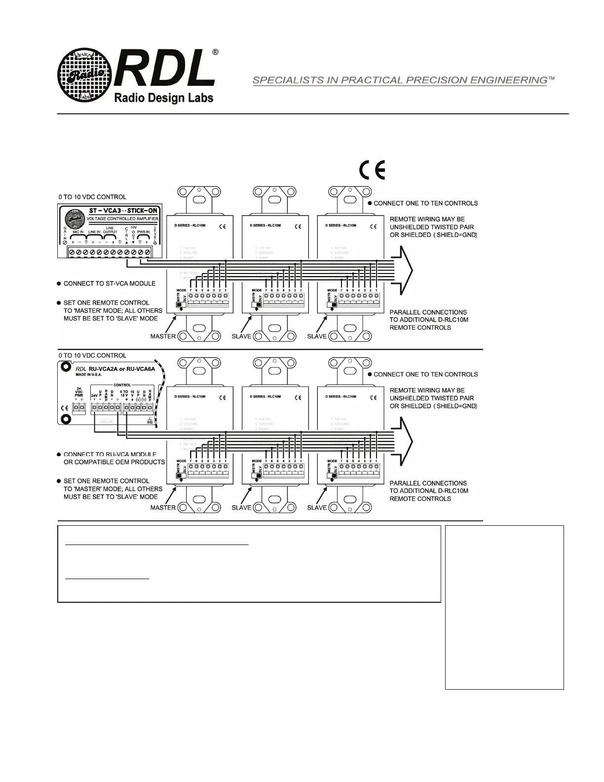
Models D-RLC10M, DS-RLC10M, DB-RLC10M
TYPICAL PERFORMANCE
Ramp: 0 to 10 Vdc (Slave mode input; Master mode output)
Pulse outputs (2): Open-Collector @ 20 mA (UP, DOWN)
Pulse duration: 500 uS (min.) to 4 mS (max.)
Pulse interval: 500 uS (min., between consecutive pulses)
Rotations, approximate min-to-max: 5 (slow rotation, no acceleration)
3 (medium rotation, with acceleration)
1 (fast rotation counterclockwise)
Level Control: Optical rotary encoder
Muting: Momentary pushbutton with LED indicator
Power Requirement: 24 Vdc @ 50 mA, Ground-referenced
Mounting: Mounts in standard US electrical box,
RDL WB- or SMB- series boxes;
cover plate available separately
Dimensions: Height: 4.11 in. 10.44 cm; Width: 1.31 in. 3.33 cm;
Depth: 0.98 in. 2.49 cm (w/o knob); Depth: 0.545 in. 3.93 cm (overall)
Installation/Operation
EN55103-1 E1-E5; EN55103-2 E1-E4
Typical Performance reflects product at publication time
exclusive of EMC data, if any, supplied with product.
Specifications are subject to change without notice.
Radio Design Labs Technical Support Centers
U.S.A. (800) 933-1780, (928) 778-3554; Fax: (928) 778-3506
Europe [NH Amsterdam] (++31) 20-6238 983; Fax: (++31) 20-6225-287
891-5610
NOTE: This equipment has been tested and
found to comply with the limits for a Class B
digital device, pursuant to part 15 of the FCC
Rule. These limits are designed to provide
reasonable protection against harmful
interference in a residential installation. The
equipment generates, uses and can radiate
radio frequency energy and, if not installed and
used in accordance with the instructions, may
cause harmful interference to radio
communications. However, there is no
guarantee that interference will not occur in a
particular installation. If this equipment does
cause harmful interference to radio or television
reception, which can be determined by turning
the equipment off an on, the user is
encouraged to try to correct the interference by
one or more of the following measures:
Reorient or relocate the receiving
antenna
Increase the separation between the
equipment and receiver
Connect the equipment into an outlet
on a circuit different from that which the
receiver is connected.
Consult the dealer or an experienced
radio/TV technician for help.
SET-UP PROGRAMMING (applicable to MASTER controls only)
Set power-up mode (last level used or preset level) during installation:
1] Press and hold the MUTE button while applying power and continue to hold for 3 seconds. This toggles the control to the opposite
mode from its last operating mode. (If it had been in preset mode, it will now be in last level used mode.)
2] LEDs 1,2,9 & 10 will flash to indicate the selected operating mode: Single Flash: Last level used mode; Double Flash: Preset mode
3] If the control is in the desired mode, begin operation; If the control is in the incorrect mode, repeat Step 1.
Storing the level in preset mode
1] Adjust the level for the desired preset level.
2] Press and hold the MUTE button for more than 3 seconds. LEDS 1,2,9 & 10 will double flash to indicate the preset level is stored.
 Loading...